dilution of flue gases.

Appliances located in confined spaces:

The confined space must be provided with two permanent openings, one commencing within 12 inches of the top and one commencing within 12 inches of the bottom of the enclosure. Each opening must have a minimum free area of one square inch per:

-1000 Btu/hr if all air is taken from inside the building.

-2000 Btu/hr if all air is taken from the outside by horizontal ducts.

-4000 Btu/hr if all air is taken from the outside by direct openings or vertical ducts.

Or the confined space must be providedwith one permanent openingor duct that is within 12 inches of the ceiling of the enclosure. This opening must have a minimum free area of one square inch per:

-3000 Btu/hr if all air is taken from the outside by a direct opening or vertical duct.

Louvers, grills and screens have a blocking effect. If the effective free area is not known, increase the sizes of your openings by 75% if your louvers are wood and by 30% if your louvers are metal. Refer to the National Fuel Gas Code for complete information. In buildings of tight construction all air should be taken from outside.

CLEARANCES

The Aquastar 125 BL is design certified for installation on a combustible wall and for installation in an alcove or closet with the minimum clearances to combustible and non - combustible construction listed below

A.Top 12 inches (306 mm)

B.Front 4 inches (102 mm)

C.Back 0 inches

D.Sides 4 inches (102mm)

E.Bottom 12 inches (306 mm)

Clearance from vent is dependent upon the clearance rating of the venting material used. For example: type B-1 vent is approved for 1 inch clearance.

Note: Minimum clearance to combustible materials should not be less than 6" for single wall flue pipe. Note that this clearance can be reduced if combustible material are protected as per table VI of the National fuel Gas Code or if Type B gas vent is used.

MOUNTING INSTALLATION

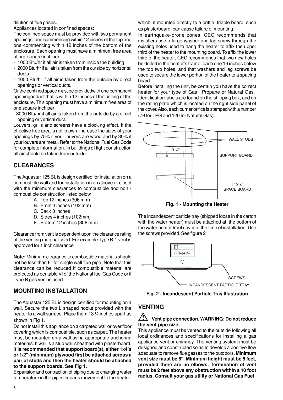
The Aquastar 125 BL is design certified for mounting on a wall. Secure the two L shaped hooks provided with the heater to a wall surface. Place them 13 ¼ inches apart as shown in Fig 1.

Do not install this appliance on a carpeted wall or over floor covering which is combustible, such as carpet. The heater must be mounted on a wall using appropriate anchoring materials. If wall is a stud wall sheathed with plasterboard, it is recommended that support board(s), either 1x4’s or 1/2" (minimum) plywood first be attached across a pair of studs and then the heater should be attached to the support boards. See Fig 1.

Expansion and contraction of piping due to changing water temperature in the pipes imparts movement to the heater

which, if mounted directly to a brittle, friable board, such as plasterboard, can cause failure of mounting.

In earthquake-prone zones, CEC recommends that installers use a large washer and lag screw through the existing holes used to hang the heater to affix the upper third of the heater to the mounting board. To affix the lower third of the heater, CEC recommends that two new holes be drilled in the heater’s frame, each one 16 inches below the top two holes, and that washers and lag screws be used to secure the lower portion of the heater to a spacing board.

Before installing the unit, be certain you have the correct heater for your type of Gas – Propane or Natural Gas. Identification labels are found on the shipping box, and on the rating plate which is located on the right side panel of the cover.Also, each burner orifice is stamped with a number (79 for LPG and 120 for Natural Gas).

WALL STUDS

13 ¼”

SUPPORT BOARD

1” X 4”

SPACE BOARD

Fig. 1 - Mounting the Heater

The incandescent particle tray (shipped loose in the carton with the water heater) must be attached at the bottom of the water heater front cover at the time of installation. Use the screws provided. See figure 2

SCREWS

INCANDESCENT PARTICLE TRAY

Fig. 2 - Incandescent Particle Tray Illustration

VENTING

Vent pipe connection. WARNING: Do not reduce the vent pipe size.

This appliance must be vented to the outside following all local ordinances and specifications for installing a gas appliance vent or chimney. The venting system must be designed and constructed so as to develop a positive flow adequate to remove flue gasses to the outdoors. Minimum vent size must be 5". Minimum height must be 6 feet, provided there are no elbows. Termination of vent must be 2 feet above any obstruction within a 10 foot radius. Consult your gas utility or National Gas Fuel

6

Page 6
Image 6
AquaStar 125B LPL, 125B NGL specifications Clearances, Mounting Installation, Venting

125B NGL, 125B LPL specifications

The AquaStar 125B LPL and 125B NGL are innovative products designed to meet the growing demands of modern aquaculture and water treatment facilities. Equipped with advanced features and technologies, these models are engineered for efficiency, performance, and sustainability, making them essential tools for aquaculture professionals and facility managers alike.

One of the standout characteristics of the AquaStar 125B series is its enhanced filtration system. Both the LPL (Low Pressure Liquid) and NGL (Natural Gas Liquid) models incorporate a high-capacity filter that effectively removes particulate matter and impurities from water. This ensures higher water quality and promotes healthier aquatic life. The filtration system is designed for easy maintenance, allowing operators to perform routine cleanings without downtime.

In addition to filtration, the AquaStar 125B series boasts a state-of-the-art aeration system. Efficient oxygenation is crucial for aquatic organisms, and these models utilize fine bubble diffusers to maximize oxygen transfer rates. This technology not only ensures that fish and other aquatic species thrive but also minimizes energy consumption, ultimately reducing operational costs.

Both models feature robust, corrosion-resistant materials, enhancing their durability in challenging environments. The casing is designed to withstand exposure to wet and humid conditions, ensuring longevity and reliability in various operational scenarios. Furthermore, the AquaStar 125B series incorporates energy-efficient motors, promoting reduced power consumption and minimizing the environmental impact.

Another innovative aspect is the intelligent monitoring system integrated into both models. The digital interface provides real-time data on water quality parameters, such as pH levels, temperature, and dissolved oxygen content. This allows for proactive management and immediate adjustments when necessary, ensuring optimal conditions for aquatic life.

Safety is also a key consideration with the AquaStar 125B series. Both models feature built-in safety protocols, including automatic shutoff mechanisms and alerts for abnormal readings, further reinforcing their reliability in managing aquatic environments.

In summary, the AquaStar 125B LPL and 125B NGL represent a leap forward in aquaculture technology, combining advanced filtration, aeration systems, and smart monitoring features. Their durable design and energy efficiency make them suitable for both commercial and non-commercial applications. These models not only improve water quality but also enhance the overall productivity of aquaculture operations while being mindful of environmental sustainability.