Connecting the pressure relief valve (PRV)

A listed pressure relief valve supplied with the heater must be installed at the time of installation. No valve is to be placed between the PRV and the heater. No reducing coupling or other restriction may be installed in the discharge line.

The discharge line must be installed such that it allows complete drainage of both the PRV and the line.

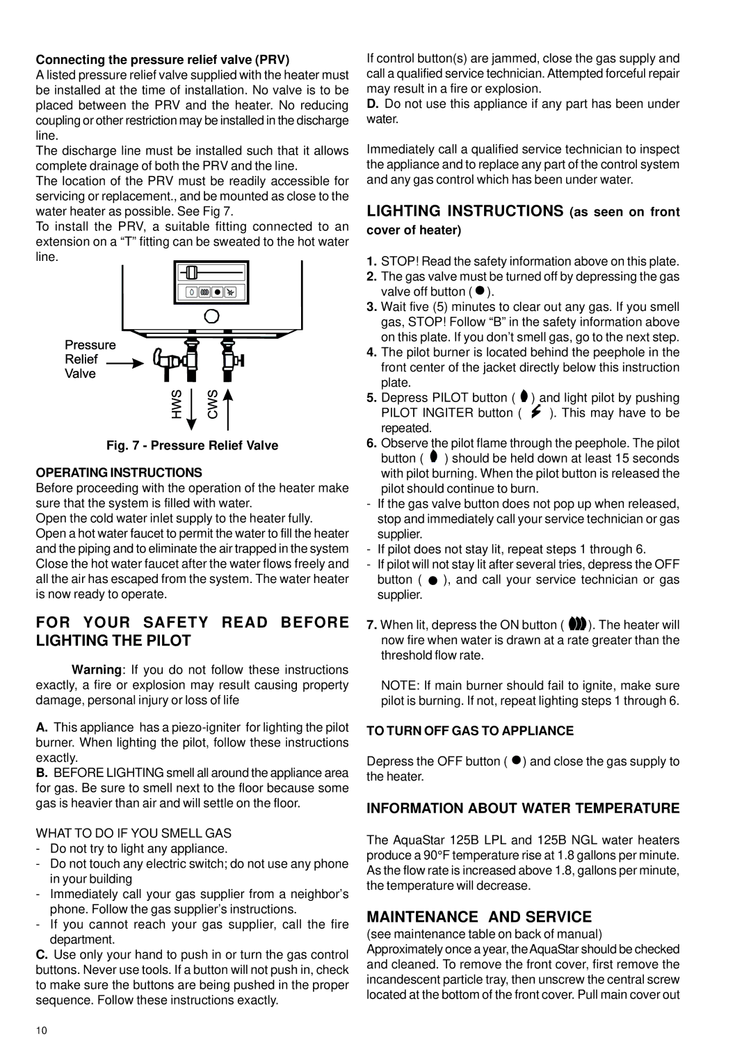
The location of the PRV must be readily accessible for servicing or replacement., and be mounted as close to the water heater as possible. See Fig 7.

To install the PRV, a suitable fitting connected to an extension on a “T” fitting can be sweated to the hot water line.

Fig. 7 - Pressure Relief Valve

OPERATING INSTRUCTIONS

Before proceeding with the operation of the heater make sure that the system is filled with water.

Open the cold water inlet supply to the heater fully. Open a hot water faucet to permit the water to fill the heater and the piping and to eliminate the air trapped in the system Close the hot water faucet after the water flows freely and all the air has escaped from the system. The water heater is now ready to operate.

FOR YOUR SAFETY READ BEFORE LIGHTING THE PILOT

Warning: If you do not follow these instructions exactly, a fire or explosion may result causing property damage, personal injury or loss of life

A.This appliance has a piezo-igniter for lighting the pilot burner. When lighting the pilot, follow these instructions exactly.

B.BEFORE LIGHTING smell all around the appliance area for gas. Be sure to smell next to the floor because some gas is heavier than air and will settle on the floor.

WHAT TO DO IF YOU SMELL GAS

-Do not try to light any appliance.

-Do not touch any electric switch; do not use any phone in your building

-Immediately call your gas supplier from a neighbor’s phone. Follow the gas supplier’s instructions.

-If you cannot reach your gas supplier, call the fire department.

C.Use only your hand to push in or turn the gas control buttons. Never use tools. If a button will not push in, check to make sure the buttons are being pushed in the proper sequence. Follow these instructions exactly.

If control button(s) are jammed, close the gas supply and call a qualified service technician. Attempted forceful repair may result in a fire or explosion.

D.Do not use this appliance if any part has been under water.

Immediately call a qualified service technician to inspect the appliance and to replace any part of the control system and any gas control which has been under water.

LIGHTING INSTRUCTIONS (as seen on front

cover of heater)

1.STOP! Read the safety information above on this plate.

2.The gas valve must be turned off by depressing the gas valve off button ( ).

3.Wait five (5) minutes to clear out any gas. If you smell gas, STOP! Follow “B” in the safety information above on this plate. If you don’t smell gas, go to the next step.

4.The pilot burner is located behind the peephole in the front center of the jacket directly below this instruction plate.

5.Depress PILOT button ( ) and light pilot by pushing

PILOT INGITER button ( ). This may have to be repeated.

6.Observe the pilot flame through the peephole. The pilot button ( ) should be held down at least 15 seconds with pilot burning. When the pilot button is released the pilot should continue to burn.

-If the gas valve button does not pop up when released, stop and immediately call your service technician or gas supplier.

-If pilot does not stay lit, repeat steps 1 through 6.

-If pilot will not stay lit after several tries, depress the OFF

button ( ), and call your service technician or gas supplier.

7.When lit, depress the ON button ( ). The heater will now fire when water is drawn at a rate greater than the threshold flow rate.

NOTE: If main burner should fail to ignite, make sure pilot is burning. If not, repeat lighting steps 1 through 6.

TO TURN OFF GAS TO APPLIANCE

Depress the OFF button ( ) and close the gas supply to the heater.

INFORMATION ABOUT WATER TEMPERATURE

The AquaStar 125B LPL and 125B NGL water heaters produce a 90°F temperature rise at 1.8 gallons per minute. As the flow rate is increased above 1.8, gallons per minute, the temperature will decrease.

MAINTENANCE AND SERVICE

(see maintenance table on back of manual) Approximately once a year, theAquaStar should be checked and cleaned. To remove the front cover, first remove the incandescent particle tray, then unscrew the central screw located at the bottom of the front cover. Pull main cover out

10

Page 10
Image 10
AquaStar 125B LPL, 125B NGL For Your Safety Read Before Lighting the Pilot, Lighting Instructions as seen on front

125B NGL, 125B LPL specifications

The AquaStar 125B LPL and 125B NGL are innovative products designed to meet the growing demands of modern aquaculture and water treatment facilities. Equipped with advanced features and technologies, these models are engineered for efficiency, performance, and sustainability, making them essential tools for aquaculture professionals and facility managers alike.

One of the standout characteristics of the AquaStar 125B series is its enhanced filtration system. Both the LPL (Low Pressure Liquid) and NGL (Natural Gas Liquid) models incorporate a high-capacity filter that effectively removes particulate matter and impurities from water. This ensures higher water quality and promotes healthier aquatic life. The filtration system is designed for easy maintenance, allowing operators to perform routine cleanings without downtime.

In addition to filtration, the AquaStar 125B series boasts a state-of-the-art aeration system. Efficient oxygenation is crucial for aquatic organisms, and these models utilize fine bubble diffusers to maximize oxygen transfer rates. This technology not only ensures that fish and other aquatic species thrive but also minimizes energy consumption, ultimately reducing operational costs.

Both models feature robust, corrosion-resistant materials, enhancing their durability in challenging environments. The casing is designed to withstand exposure to wet and humid conditions, ensuring longevity and reliability in various operational scenarios. Furthermore, the AquaStar 125B series incorporates energy-efficient motors, promoting reduced power consumption and minimizing the environmental impact.

Another innovative aspect is the intelligent monitoring system integrated into both models. The digital interface provides real-time data on water quality parameters, such as pH levels, temperature, and dissolved oxygen content. This allows for proactive management and immediate adjustments when necessary, ensuring optimal conditions for aquatic life.

Safety is also a key consideration with the AquaStar 125B series. Both models feature built-in safety protocols, including automatic shutoff mechanisms and alerts for abnormal readings, further reinforcing their reliability in managing aquatic environments.

In summary, the AquaStar 125B LPL and 125B NGL represent a leap forward in aquaculture technology, combining advanced filtration, aeration systems, and smart monitoring features. Their durable design and energy efficiency make them suitable for both commercial and non-commercial applications. These models not only improve water quality but also enhance the overall productivity of aquaculture operations while being mindful of environmental sustainability.