NOTE: The gas pressures specified below refer to pressures taken at the pressure tap on the gas inlet pipe just above the regulator (See Fig 4). These readings should be taken while the heater is operating at full input — i.e. with the gas control positioned all the way to the right.

MAXIMUM INLET GAS FLOW PRESSURE SETTING

Altitude

Natural Gas

Liquid Propane


inches W.C:

inches W.C:

0' - 2.000 ft

5.7"

10.5"

2.000 ft - 4.500 ft

4.6"

8.4"

Above 4.500 ft consult your local gas supplier.

GAS LINE SIZING

-It is strongly recommended that the Natural Gas pipe be Black Iron pipe the entire distance from the outside meter to the inlet of the Aquastar regulator. 1/2” Black Iron pipe up to 10 feet, 3/4” Black Iron pipe up to 40 feet and 1” Black Iron pipe up to 150 feet distances. Flex line tubing is NOT recommended, but if used then oversize it.

-It is strongly recommended that the LP Gas pipe be semi-rigid copper or Black Iron pipe from the outside regulator to the inlet of the Aquastar regulator. For semi-rigid copper piping: 5/8” up to 20 feet and 3/4” up to 60 feet distances. For Black Iron piping: 1/2” up to 45 feet and 3/4” up to 160 feet distances. Flex line tubing is NOT recommended, but if used then oversize it.

THESE FIGURES ARE FOR AQUASTAR SUPPLY ONLY, ALL OTHER APPLIANCES IN THE BUILDING WILL NEED TO BE INCLUDED IN THE PIPE SIZING.

National Fuel Gas Code requires that a sediment trap (drip leg) be installed on gas appliances not so equipped. The drip leg must be accessible and not subject to freezing conditions. Install in accordance with the recommendations of the serving gas supplier.

WARNING: The heater must be disconnected from the gas supply piping system during any pressure testing of that system at test pressures in excess of 0.5 psig.

The water heater must be isolated from the gas supply piping system by closing the manual shutoff valve during any pressure testing of the gas supply piping system at test pressures equal to or more than 0.5 psig.

The water heater, including the pressure regulator provided with it, must not be operated at gas supply pressures in excess of 0.5 psig. If overpressure has occurred, such as through improper testing of the gas lines or malfunction of the supply system, the gas valve and regulator must be checked for safe operation. Make sure that the regulator vent is protected against blockage.

When your connections are made, check for gas leaks at all joints (not just the ones you made). Apply some soapy water to all gas fittings and gas valve. Soap bubbles are a sign of a leak.

NOTE: Do not apply soap solution to pilot filter screen or pilot orifice area. If you have a leak, shut off the gas. After verifying that required gaskets are in place, tighten appropriate fittings to stop leak. Turn the gas on and check again with a soapy solution. Never test for gas leaks using a match or flame.

WATER CONNECTIONS

When facing the heater, the cold water inlet is on your right and the hot water outlet is on your left.

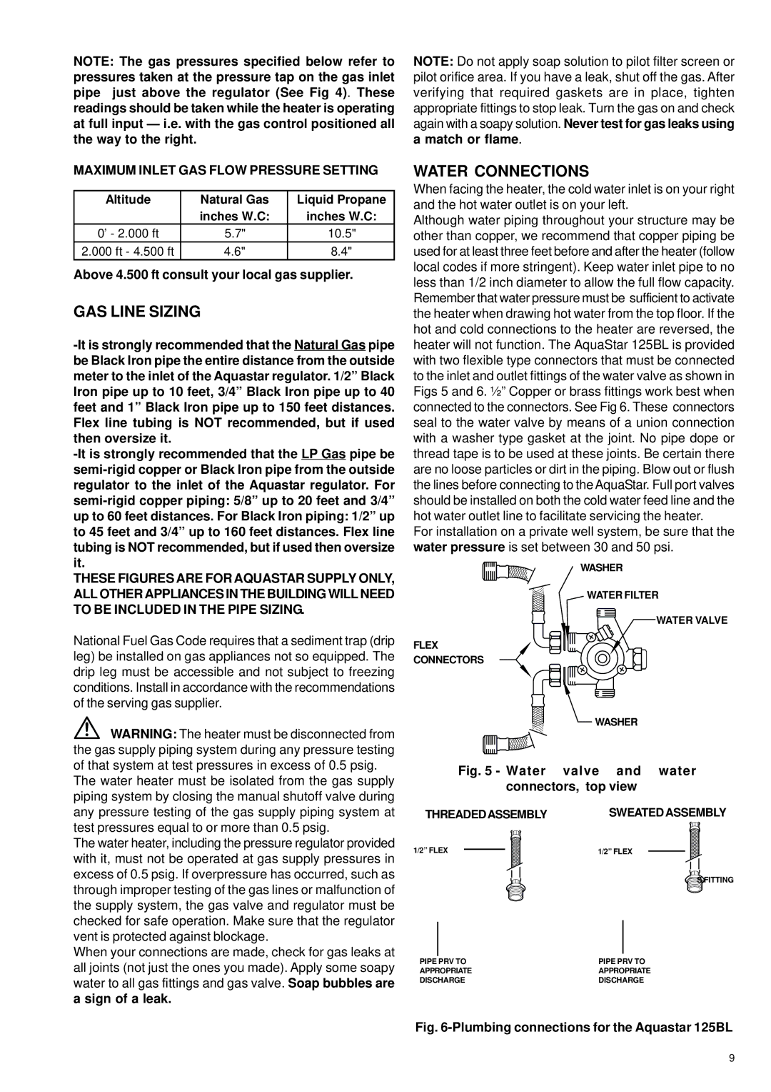
Although water piping throughout your structure may be other than copper, we recommend that copper piping be used for at least three feet before and after the heater (follow local codes if more stringent). Keep water inlet pipe to no less than 1/2 inch diameter to allow the full flow capacity. Remember that water pressure must be sufficient to activate the heater when drawing hot water from the top floor. If the hot and cold connections to the heater are reversed, the heater will not function. The AquaStar 125BL is provided with two flexible type connectors that must be connected to the inlet and outlet fittings of the water valve as shown in Figs 5 and 6. ½” Copper or brass fittings work best when connected to the connectors. See Fig 6. These connectors seal to the water valve by means of a union connection with a washer type gasket at the joint. No pipe dope or thread tape is to be used at these joints. Be certain there are no loose particles or dirt in the piping. Blow out or flush the lines before connecting to the AquaStar. Full port valves should be installed on both the cold water feed line and the hot water outlet line to facilitate servicing the heater.

For installation on a private well system, be sure that the water pressure is set between 30 and 50 psi.

WASHER

WATER FILTER

WATER VALVE

FLEX

CONNECTORS

WASHER

Fig. 5 - Water valve and water connectors, top view

THREADEDASSEMBLY SWEATED ASSEMBLY

1/2” FLEX

1/2” FLEX

SFITTING

PIPE PRV TO

PIPE PRV TO

APPROPRIATE

APPROPRIATE

DISCHARGE

DISCHARGE

Fig. 6-Plumbing connections for the Aquastar 125BL

9

Page 9
Image 9
AquaStar 125B NGL, 125B LPL specifications GAS Line Sizing, Water Connections, Maximum Inlet GAS Flow Pressure Setting

125B NGL, 125B LPL specifications

The AquaStar 125B LPL and 125B NGL are innovative products designed to meet the growing demands of modern aquaculture and water treatment facilities. Equipped with advanced features and technologies, these models are engineered for efficiency, performance, and sustainability, making them essential tools for aquaculture professionals and facility managers alike.

One of the standout characteristics of the AquaStar 125B series is its enhanced filtration system. Both the LPL (Low Pressure Liquid) and NGL (Natural Gas Liquid) models incorporate a high-capacity filter that effectively removes particulate matter and impurities from water. This ensures higher water quality and promotes healthier aquatic life. The filtration system is designed for easy maintenance, allowing operators to perform routine cleanings without downtime.

In addition to filtration, the AquaStar 125B series boasts a state-of-the-art aeration system. Efficient oxygenation is crucial for aquatic organisms, and these models utilize fine bubble diffusers to maximize oxygen transfer rates. This technology not only ensures that fish and other aquatic species thrive but also minimizes energy consumption, ultimately reducing operational costs.

Both models feature robust, corrosion-resistant materials, enhancing their durability in challenging environments. The casing is designed to withstand exposure to wet and humid conditions, ensuring longevity and reliability in various operational scenarios. Furthermore, the AquaStar 125B series incorporates energy-efficient motors, promoting reduced power consumption and minimizing the environmental impact.

Another innovative aspect is the intelligent monitoring system integrated into both models. The digital interface provides real-time data on water quality parameters, such as pH levels, temperature, and dissolved oxygen content. This allows for proactive management and immediate adjustments when necessary, ensuring optimal conditions for aquatic life.

Safety is also a key consideration with the AquaStar 125B series. Both models feature built-in safety protocols, including automatic shutoff mechanisms and alerts for abnormal readings, further reinforcing their reliability in managing aquatic environments.

In summary, the AquaStar 125B LPL and 125B NGL represent a leap forward in aquaculture technology, combining advanced filtration, aeration systems, and smart monitoring features. Their durable design and energy efficiency make them suitable for both commercial and non-commercial applications. These models not only improve water quality but also enhance the overall productivity of aquaculture operations while being mindful of environmental sustainability.