MASONRY CHIMNEY: Masonry chimneys shall be built and installed in accordance with NFPS 211 or local codes. A minimum 5” diameter gas vent pipe (metal double wall Type B), or an approved clay flue liner or a listed chimney lining system must be used when venting into a naturally drafting, internal masonry chimney. 6 inch is required in elevations greater than 2000 feet, see Fig. 4. Local codes may require the use of both gas vent and an approved lining system when venting into a masonry chimney. The Commonwealth of Massachusetts requires the use of a listed liner. Lining systems include approved clay flue lining, a listed chimney lining system or other approved material that will resist corrosion, erosion, softening, or cracking from exhaust flue gases at temperatures up to 1800 degrees F. The lining system must be listed for use with naturally drafting, draft hood equipped gas appliances. Follow local codes and refer to NFGC 54 and NFPA 58.
When connecting the water heater to a masonry chimney the following connector guidelines must be followed for safe and proper operation: An approved gas vent connector must be attached to the top of the water heater and rise vertically at least 12” before entering into an approved gas vent connector elbow. Any gas vent section that is greater than 45 degrees from the vertical is considered horizontal. If a horizontal vent connector is to be used to connect the vertical gas vent connector on the top of the water heater to the masonry chimney, that approved horizontal gas vent connector must be kept as short as possible and must be sloped upwards at least ¼” per foot of its length. This connector must be supported throughout its horizontal length. This horizontal gas vent connection may be no greater than 75% of the total vertical gas flue vent within the chimney. Also, an approved thimble or collar must be used when penetrating a masonry chimney.
A) Existing INTERIOR Masonry Chimney
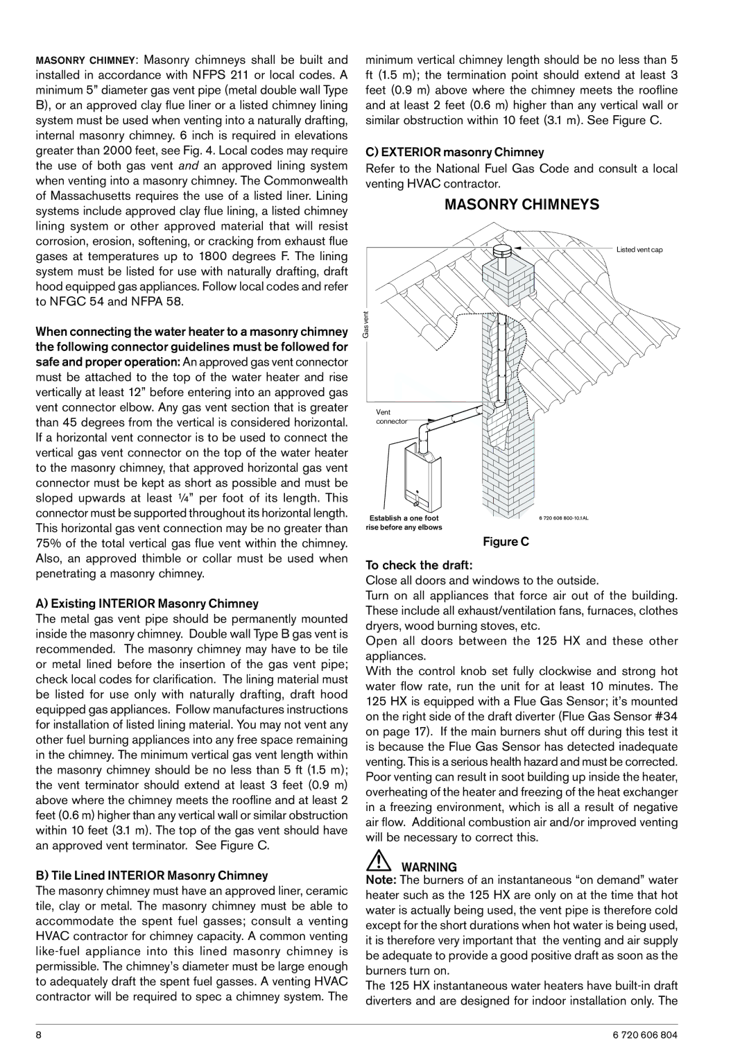
The metal gas vent pipe should be permanently mounted inside the masonry chimney. Double wall Type B gas vent is recommended. The masonry chimney may have to be tile or metal lined before the insertion of the gas vent pipe; check local codes for clarification. The lining material must be listed for use only with naturally drafting, draft hood equipped gas appliances. Follow manufactures instructions for installation of listed lining material. You may not vent any other fuel burning appliances into any free space remaining in the chimney. The minimum vertical gas vent length within the masonry chimney should be no less than 5 ft (1.5 m); the vent terminator should extend at least 3 feet (0.9 m) above where the chimney meets the roofline and at least 2 feet (0.6 m) higher than any vertical wall or similar obstruction within 10 feet (3.1 m). The top of the gas vent should have an approved vent terminator. See Figure C.
B) Tile Lined INTERIOR Masonry Chimney
The masonry chimney must have an approved liner, ceramic tile, clay or metal. The masonry chimney must be able to accommodate the spent fuel gasses; consult a venting HVAC contractor for chimney capacity. A common venting
minimum vertical chimney length should be no less than 5 ft (1.5 m); the termination point should extend at least 3 feet (0.9 m) above where the chimney meets the roofline and at least 2 feet (0.6 m) higher than any vertical wall or similar obstruction within 10 feet (3.1 m). See Figure C.
C) EXTERIOR masonry Chimney
Refer to the National Fuel Gas Code and consult a local venting HVAC contractor.
MASONRY CHIMNEYS
Listed vent cap
Gas vent
Vent connector![]()
Establish a one foot rise before any elbows
Figure C
To check the draft:
Close all doors and windows to the outside.
Turn on all appliances that force air out of the building. These include all exhaust/ventilation fans, furnaces, clothes dryers, wood burning stoves, etc.
Open all doors between the 125 HX and these other appliances.
With the control knob set fully clockwise and strong hot water flow rate, run the unit for at least 10 minutes. The 125 HX is equipped with a Flue Gas Sensor; it’s mounted on the right side of the draft diverter (Flue Gas Sensor #34 on page 17). If the main burners shut off during this test it is because the Flue Gas Sensor has detected inadequate venting. This is a serious health hazard and must be corrected. Poor venting can result in soot building up inside the heater, overheating of the heater and freezing of the heat exchanger in a freezing environment, which is all a result of negative air flow. Additional combustion air and/or improved venting will be necessary to correct this.
WARNING
Note: The burners of an instantaneous “on demand” water heater such as the 125 HX are only on at the time that hot water is actually being used, the vent pipe is therefore cold except for the short durations when hot water is being used, it is therefore very important that the venting and air supply be adequate to provide a good positive draft as soon as the burners turn on.
The 125 HX instantaneous water heaters have built-in draft diverters and are designed for indoor installation only. The
8 | 6 720 606 804 |
