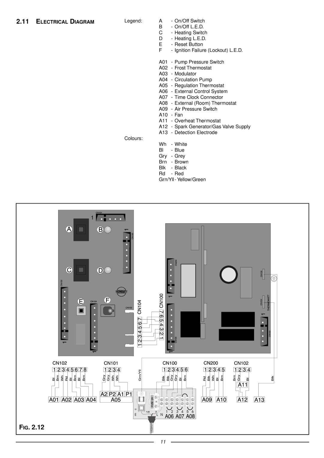
41-116-05 specifications
The Ariston 41-116-05 is an innovative and efficient appliance designed to meet modern home heating and comfort needs. As part of Ariston's extensive portfolio, this model embodies the brand's commitment to quality and sustainability.One of the main features of the Ariston 41-116-05 is its advanced energy efficiency rating. It incorporates cutting-edge technology to optimize energy consumption, helping homeowners reduce their utility bills while minimizing their environmental impact. This aligns with the growing demand for eco-friendly heating solutions in today's market.
The heater is equipped with a powerful heating element, capable of quickly generating warmth even in larger spaces. Its robust performance ensures that rooms reach the desired temperature rapidly, providing comfort during cold weather conditions. The unit is designed with multiple heat settings, allowing users to customize the warmth level according to their preferences and specific needs.
Moreover, the Ariston 41-116-05 features an intuitive digital control panel. This user-friendly interface makes it easy for individuals to adjust settings, monitor energy consumption, and set timers for automatic operation. Some models also offer Wi-Fi connectivity, enabling users to control their heating remotely via a smartphone app. This feature is particularly beneficial for those who want to maintain a comfortable environment in their homes while controlling energy use.
Safety is another cornerstone of the Ariston 41-116-05’s design. The appliance is equipped with multiple safety mechanisms, including overheat protection and a tip-over switch. These features ensure that the unit operates safely and securely, providing peace of mind for homeowners.
In summary, the Ariston 41-116-05 is a modern appliance that combines efficiency, performance, and safety. Its exceptional energy-saving capabilities, user-friendly controls, and robust heating power make it an ideal choice for anyone seeking reliable home heating solutions. With its range of features and commitment to sustainability, the Ariston 41-116-05 stands out as a valuable addition to contemporary households, enhancing comfort while being mindful of the environment.

