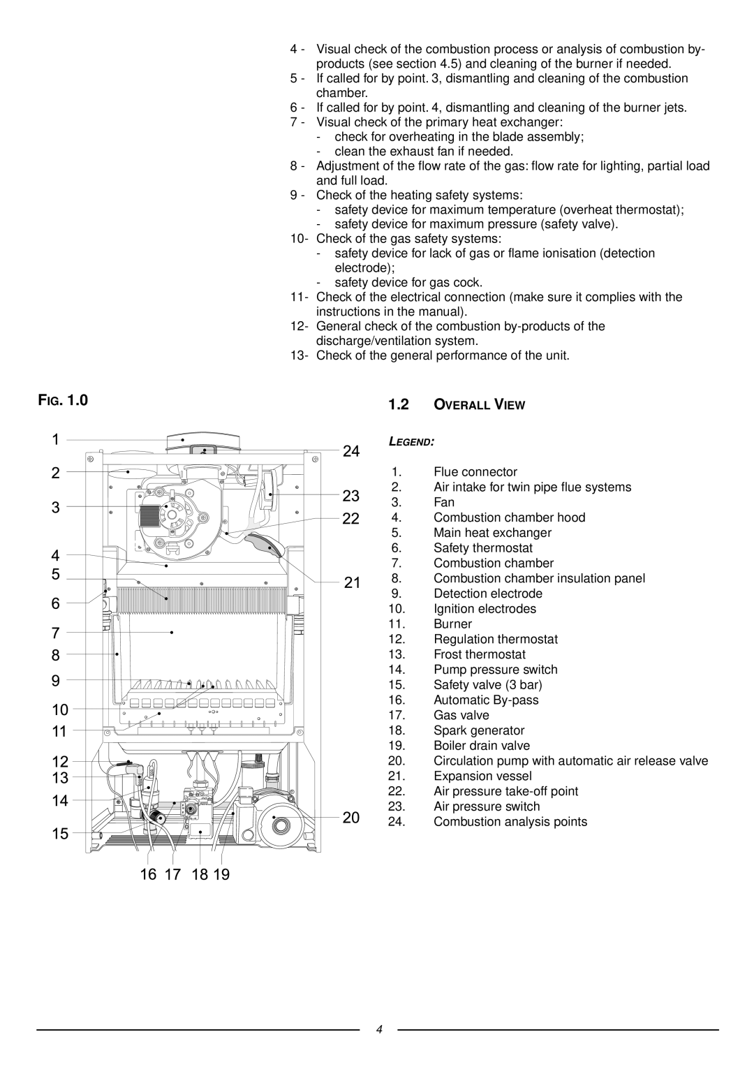
41-116-07 specifications
The Ariston 41-116-07 is a highly efficient and reliable appliance designed to meet the diverse needs of modern households. This model is primarily recognized for its robust build quality and energy-efficient performance, making it a popular choice among consumers looking for sustainability without sacrificing functionality.One of the standout features of the Ariston 41-116-07 is its advanced heating technology. The appliance utilizes a high-performance heating element that ensures rapid heating and consistent temperature control. This means that users can enjoy hot water and comfort quickly, with minimal wait times. The innovative design also includes insulation that helps to maintain heat, reducing energy consumption and lowering utility bills.
User convenience is another hallmark of the Ariston 41-116-07. The appliance comes equipped with an intuitive control panel that allows for easy operation. The simple interface helps users to set their desired temperature and monitor performance effortlessly. Additionally, the model includes programmable settings, enabling users to schedule heating cycles according to their lifestyles, further enhancing energy savings.
Safety features are paramount in the design of the Ariston 41-116-07. The appliance includes a range of safety mechanisms such as automatic shut-off, preventing overheating and potential hazards. The built-in sensors continuously monitor the system's operation, ensuring optimal performance while safeguarding the user's home and family.
In terms of installation, the Ariston 41-116-07 excels with its compact size and flexible mounting options. It can be conveniently installed in various locations, whether in a utility room, kitchen, or bathroom, without requiring extensive modifications. This flexibility is ideal for homes with limited space or unique layouts.
Maintenance is also simplified with the Ariston 41-116-07. The appliance is designed with easy-access components, making routine maintenance or troubleshooting straightforward for the average user. This ease of care further contributes to its reputation for reliability, ensuring that the unit operates efficiently over its lifespan.
In summary, the Ariston 41-116-07 stands out for its energy efficiency, user-friendly features, safety mechanisms, versatile installation options, and low maintenance requirements. These characteristics make it a valuable addition to any modern home, catering to the needs of consumers seeking both performance and convenience in their appliances. Whether for daily use or occasional needs, the Ariston 41-116-07 guarantees satisfaction through its innovative technologies and thoughtful design.

