Operating Manual -
FR Features (FR-8 not shown)
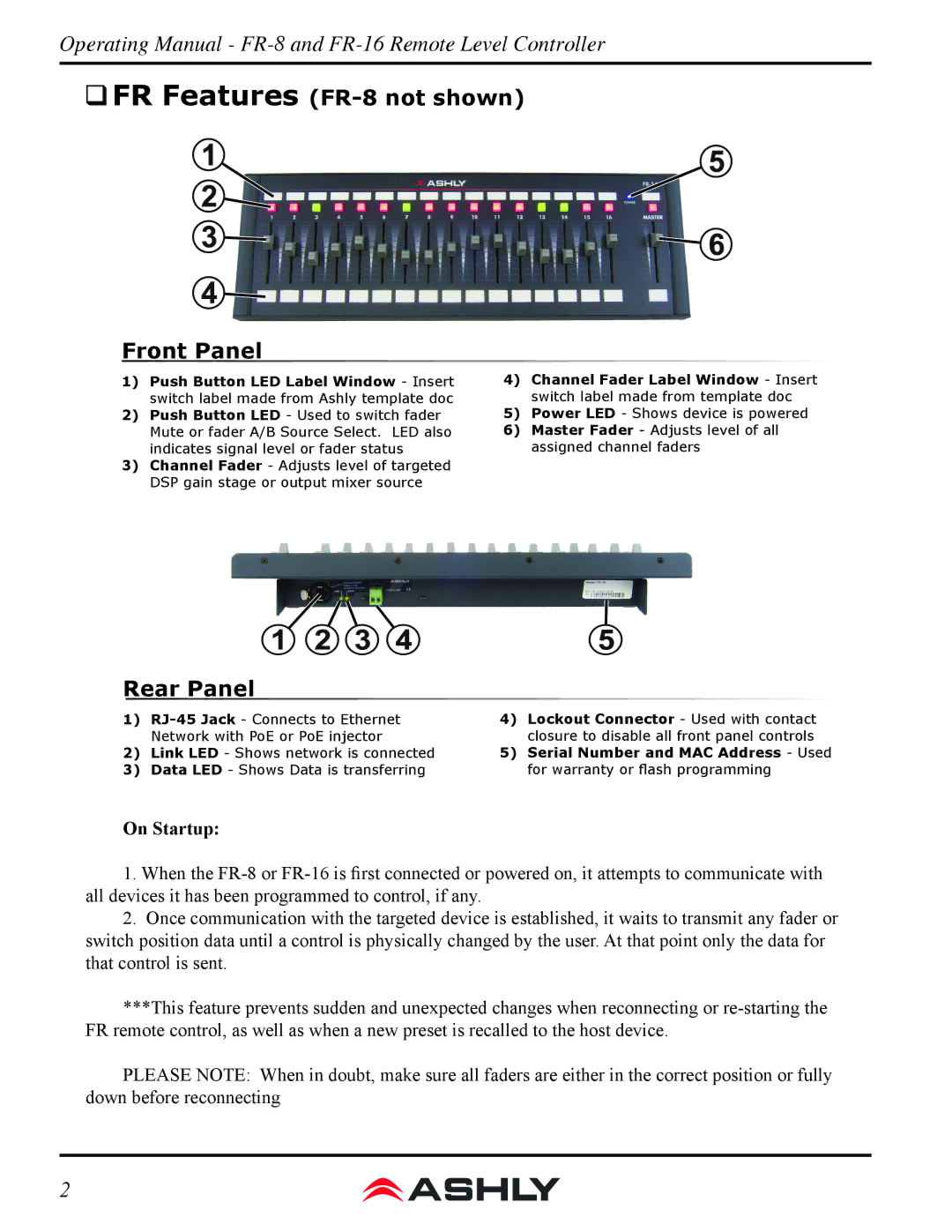
Front Panel
1)Push Button LED Label Window - Insert switch label made from Ashly template doc
2)Push Button LED - Used to switch fader Mute or fader A/B Source Select. LED also indicates signal level or fader status
3)Channel Fader - Adjusts level of targeted DSP gain stage or output mixer source
4)Channel Fader Label Window - Insert switch label made from template doc
5)Power LED - Shows device is powered
6)Master Fader - Adjusts level of all assigned channel faders
Rear Panel
1)
2)Link LED - Shows network is connected
3)Data LED - Shows Data is transferring
4)Lockout Connector - Used with contact closure to disable all front panel controls
5)Serial Number and MAC Address - Used for warranty or flash programming
On Startup:
1.When the
2.Once communication with the targeted device is established, it waits to transmit any fader or switch position data until a control is physically changed by the user. At that point only the data for that control is sent.
***This feature prevents sudden and unexpected changes when reconnecting or
PLEASE NOTE: When in doubt, make sure all faders are either in the correct position or fully down before reconnecting
2