MFA-6000, MFA-8000 specifications
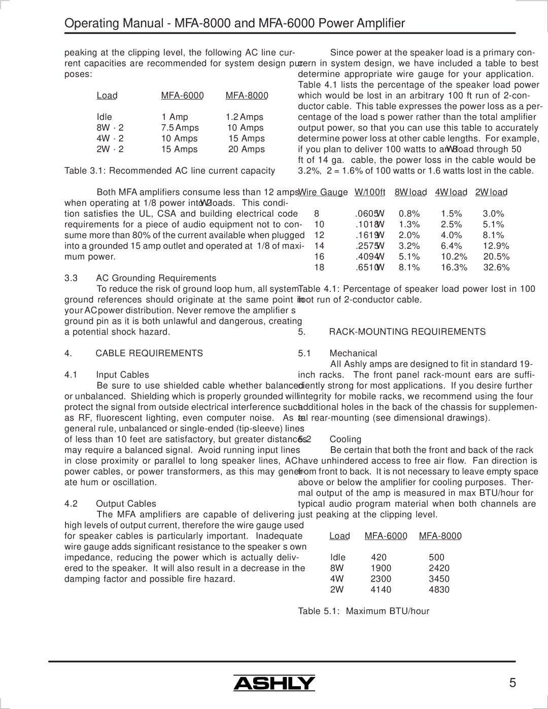
The Ashly MFA-8000 is a state-of-the-art audio amplifier designed for both professional and commercial audio applications. Renowned for its reliability, sound quality, and versatility, this amplifier is perfect for installation in concert halls, theaters, houses of worship, and various other venues that require robust audio performance.One of the standout features of the MFA-8000 is its impressive power output. Delivering 800 watts per channel at 4 ohms, the amplifier is capable of driving demanding speaker systems with ease, ensuring that sound reproduction remains crisp and clear, even at high volumes. This power is complemented by a dynamic range that enhances the listening experience, making it suitable for music playback, public announcements, and other audio applications.
The MFA-8000 incorporates Class AB amplification technology, which is known for its low distortion and high linearity. This ensures that the audio signal remains faithful to the source material, providing an authentic listening experience. Additionally, the amplifier includes advanced protection circuits that safeguard against overloads, short circuits, and overheating, ensuring longevity and durability.
In terms of connectivity, the MFA-8000 offers a variety of input options, including XLR, 1/4" TRS, and RCA connectors, making it highly versatile and compatible with a wide range of audio sources. The rear panel features an intuitive layout that simplifies the connection process, allowing users to easily integrate the amplifier into existing audio setups.
Furthermore, the MFA-8000 is equipped with built-in signal processing capabilities, including adjustable crossover settings and EQ controls, allowing users to tailor the output to suit the specific acoustics of their venue. This adaptability makes it an excellent choice for installations where sound quality must be optimized for different settings or events.
Cooling is also a critical aspect of the MFA-8000’s design. The amplifier features a highly efficient cooling system with variable-speed fans that ensure the unit remains cool even during prolonged use, preventing thermal issues that could compromise performance.
Overall, the Ashly MFA-8000 is a powerful and reliable audio amplifier that combines advanced technologies with practical features, making it an ideal solution for a wide range of professional audio applications. Its robust construction, high-quality sound reproduction, and user-friendly design make it a valuable addition to any audio setup, ensuring that it meets the demands of both sound engineers and everyday users alike.

