Aspire 4625/4625G Series Service Guide
Revision History
III
Copyright
Conventions
Preface
Page
Table of Contents
Viii
Troubleshooting 107
Microsoft Windows 7 Environment Test
Aspire 4625/4625G
Table of Contents
Chapter
Features
Audio
Dimensions and weight
Storage
Optical Drive
Special keys and controls
Power adapter and battery
Interface
Software
Optional Items
Environment
Warranty
AMD Champlain
System Block Diagram
Icon Description
Your Acer Aspire Notebook tour
Front View
HDD
Hdmi
Closed Front View
Left View
Bottom View
Right View
Icon Function Description
Indicators
Function Left Button Right Button Main TouchPad
TouchPad Basics
Desired access Num Lock on Num Lock off
Using the Keyboard
Lock Keys and embedded numeric keypad
Lock key Description
Key Description
Windows Keys
Hotkey Icon Function Description
Hot Keys
Part
Hardware Specifications and Configurations
Skew Comparison
Processor Specifications
Specification
Cores Bus Cache Package Acer P/N Speed
Size Voltage
4GB
System Memory Specification
1M SPI ROM
Memory Combinations Slot Total Memory
System Board Major Chips Specification
Ports Specification
Bluetooth Specification
Wireless Module Specification
LAN Module Specification
Hgst
Hard Disk Drive Interface Specification
RPM
Sata
Super-Multi Drive Module
Keyboard Controller Specification
Audio Interface Specification
Battery Specification Cell
RTC Battery Specification
System LED Indicator Specification
AC Adapter Specification
LCD Specification
LG LP140WH2-TLA2/LP140WH2-TLL1/LP140WH2-TLL1
Video Interface Specification
LCD Display Supported Resolution Bits
Hdmi Port Specification
GDDR3
Pcmcia Port Not available in this model
Card Reader Specification
LCD Inverter Not available with this model
Page
Chapter
Navigating the Bios Utility
Bios Setup Utility
Information
Aspire JV41 Bios
Parameter Description
Uuid
Main
Disabled
Parameter Description Format/Option
Sata Class ID
Security
Disabled or
Parameter Description Option
Clear or Set
Removing a Password
Setting a Password
USB Cdrom
Boot
Exit
Security Boot Exit Exit Saving Changes
Bios Flash Utilities
DOS Flash Utility
WinFlash Utility
Remove HDD Password
Remove HDD/BIOS Password Utilities
Removing Bios Passwords
Chapter
Clearing Bios Passwords
Using DMITools
Using Boot Sequence Selector
Run UUID.bat
Configuring Uuid Values
Disassembly Requirements
Machine Disassembly and Replacement
Disassembly Process
Pre-disassembly Instructions
General Information
Main Screw List Quantity Part Number
Screw List Step Quantity
External Module Disassembly Process
External Modules Disassembly Flowchart
Removing the Battery Pack
Removing the SD dummy card
Step Size Quantity Screw Type Lower Cover M2.5*6.5
Removing the Lower Cover
Step Size Quantity Screw Type ODD Module M2.5*3
Removing the Optical Drive Module
Step Size Quantity Screw Type ODD Bracket M2.0*3
Removing the Dimm Modules
Step Size Quantity Screw Type Wlan Board M2.0*3
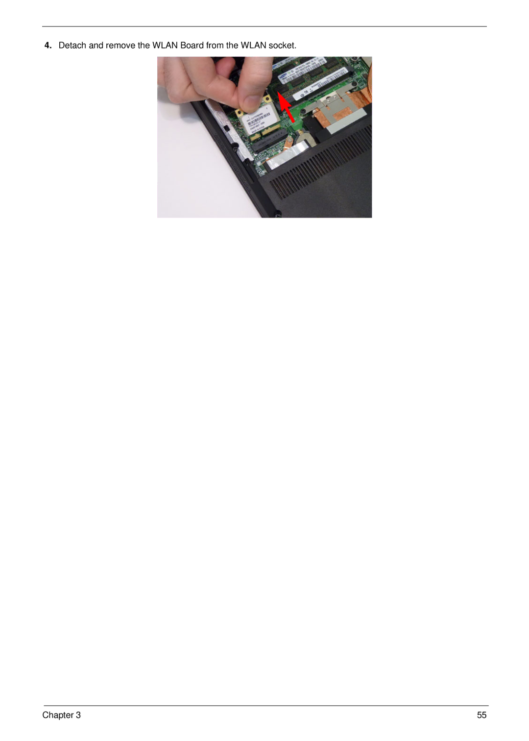
Removing the Wlan Module
Page
Step Size Quantity Screw Type HDD Carrier M3.0*3
Removing the Hard Disk Drive Module
Main Unit Disassembly Flowchart
Main Unit Disassembly Process
Removing the Keyboard
Removing the Upper Cover
Chapter
Step Size Quantity Screw Type
Removing the Power Switch Board
Removing the Function Board
Step Size Quantity Screw Type Function Board M2.0*3widehead
Step Size Quantity Screw Type USB Board M2.5*4
Removing the USB Board
Step Size Quantity Screw Type Bluetooth Board M2.0*3
Removing the Bluetooth Module
Removing the LCD Module
Chapter
Step Size Quantity Screw Type
Removing the Mainboard
Step Size Quantity Screw Type Mainboard M2.5*4
Removing the Thermal Module
Step Size Quantity Screw Type Thermal Module M2.0*3
Removing the CPU
Removing the PCH Thermal Module
Removing the RTC Battery
LCD Module Disassembly Flowchart
LCD Module Disassembly Process
Step Size Quantity Screw Type LCD Bezel M2.5*4
Removing the LCD Bezel
Removing the Camera Module
Step Size Quantity Screw Type LCD Panel M2.0*3
Removing the LCD Panel
Removing the FPC Cable
Removing the Microphone Module
Removing the Antennas
Step Size Quantity Screw Type LCD Hinges M2.5*3
Removing the Hinges
Replacing the MIC and WiFi Antennas
LCD Module Reassembly Procedure
Replacing the FPC Cable
Replacing the LCD Panel
Replacing the Webcam
Replacing the LCD Bezel
Replacing the CPU
Main Module Reassembly Procedure
Replacing the RTC Battery
Replacing the Thermal Module
Replacing the PCH Thermal Module
Chapter
Replacing the LCD Module
Page
Chapter
Replacing the Bluetooth Module
Replacing the USB Board
Replacing the Function Board
Replacing the Power Switch Board
Replacing the Upper Cover
Page
100 Chapter
Replacing the Keyboard
Replacing the Hard Disk Drive Module
Replacing the ODD Module
Page
Insert the Wlan board into the Wlan socket
Replacing the Wlan Board
Replacing the Dimm Modules
Replacing the Lower Covers
Replacing the Dummy Cards
Replacing the Battery Pack
Symptoms Verified Go To
Common Problems
Computer Shutsdown Intermittently
Power On Issue
No Post or Video
No Display Issue
Abnormal Video Display
Random Loss of Bios Settings
Built-In Keyboard Failure
LCD Failure
Internal Speaker Failure
TouchPad Failure
Select Set up microphone
Sound Problems
Microphone Problems
Select Startup Repair
HDD Not Operating Correctly
Select Repair your computer
ODD Not Operating Correctly
ODD Failure
Discs Do Not Play
Drive Not Detected
Thermal Unit Failure
Wireless Function Failure
Other Failures
External Mouse Failure
Dimm
Intermittent Problems
Undetermined Problems
Code Beeps Post Routine Description
Post Codes
Code Post Routine Description
122 Chapter
Code Beeps Post Routine Description
Code Beeps For Boot Block in Flash ROM
U10/EC/KBC
Top View
PU14/3V/5V PWM IC
Clearing Password Check
Clearing Password Check and Bios Recovery
Steps for Clearing Bios Password Check
Clear Cmos Jumper
Bios Recovery Boot Block
Bios Recovery by Crisis Disk
Bios Recovery Hotkey
Steps for Bios Recovery from USB Storage
FRU Field Replaceable Unit List
Description Acer P/N
Aspire 4625/4625G Exploded Diagrams
LCD Assembly
Chassis Assembly
ZQ1 ZR6FBZR6004,REV MBSG,PARK,SAM,BT WO Cpuassy
HDD-BKT
Wwan Minicard BEVT-22A23T0 STN
BSQ
Category Partname Description Adapter
Battery
FRU List
Cables
Category Partname Description
Power Cordeu 1.8M ZR1 Power
Power Cord US 3PIN Rohs ZB1 PWR Cord US
PIN Brazil 3P S/P Power Cord UK 3PIN ET2S Power
Cord S/P-UK Power Cord Italian 3PIN EI2 Power Cord
CPU/Processor
Category Partname Description Case/Cover/Bracket/Assembly
HDD/Hard Disk Drive
Category Partname Description DVD RW Drive
MK3265GSX-EUL MK3265GSX Sata 8MB LF F
WD3200BEVT
ML320M,WD Sata 8MB LF F BEVT-22A0RT0 S.P
MK5065GSX-EUL BS, 320G/P Sata 8MB LF F
Category Partname Description Keyboard
ZQ1 K/BSWEDISH
ZQ1 K/BSPANISH
ZQ1 K/BSWISS
ZQ1 K/BTHAI S.P
Category Partname Description LCD Module
Reader W/O CPU MBAMD,UMA,W/O CPUS.P MB AMD Park W/CARD ZQ2B
Category Partname Description Mainboard
MB AMD UMA W/CARD ZQ2B
Category Partname Description Memory
Miscellaneous
Category Partname Description Heatsink
Part Name Description
Screw List
Model Country Acer Description
Appendix a
Aspire 4625/4625G
AS4625G-N834G64Mn W7HP64ATSG1 MC
S2.PSS0
Acla LX.PSS0
Parkxt
Model Country Acer Part No BOM Name
VGA Chip
LX.PSH02.024 AS4625GPARKXT512 APP920
UMA
Acla
SO2GBIII10
Model Country Acer Part No
SO2GBIII10 SO4GBIII10
SO1GBIII10 SO2GBIII10
SO2GBIII10 SO1GBIII10
SO4GBIII10 SO2GBIII10
SO1GBIII10
NSM8XS9.5
HDD 1GB ODD
AS4625G-P922G50Mn
AS4625-N834G32Mn Singapore LX.PSS02.016 N320GB5.4KS
Appendix B
Test Compatible Components
Audio Codec
Microsoft Windows 7 Environment Test
Vendor Type Description Cover
Vendor Type Description
Digi LF F/WGJ002J
Digi
22A0RT0, ML320M,WD Sata 8MB LF F
Hgst SG
CMO
NLED14WXGAG
AUO
SO2GBIII13
NB Chipset
Modem
SB Chipset
Side Port
Wireless LAN
WiFi Antenna
164
Appendix C
Online Support Information
166
Index
168