Aspire 5336 Series Service Guide
Revision History
Copyright
III
Page
Conventions
Preface
Table of Contents
139
Viii
AS5336
Microsoft Windows 7 Environment Test
Table of Contents
Features
Chapter
Storage
Dimensions and Weight
Audio
Optical Media Drive
Interface
Power Subsystem
Special Keys and Controls
Software
Optional Items
Environment
System Block Diagram
Intel Penryn Processor
Icon Description
Your Acer Notebook tour
Front View
HDD
Closed Front View
Closed Rear View
Right View
Left View
Hdmi
Base View
Indicators
Icon Function Description
Touchpad Basics
Function Left Button Right Button Main Touchpad
Lock Keys and embedded numeric keypad
Using the Keyboard
Lock key Description
Windows Keys
Key Description
Hot Keys
Hotkey Icon Function Description
Hardware Specifications and Configurations
Hard Disk Drive Interface Specification
System Memory Specification
Memory Combinations Slot Total Memory
WD3200BEVT
WD2500BEVT
MK2565GSX
MK3265GSX
WD6400BEVT MK6465GSX WD7500BPVT WD3200BPVT
WD5000BEVT
MK5065GSX
22HXZT1 22ZEST0
Super-Multi Drive Interface Specification
BD Drive Interface Specification
Bluetooth Interface Specification
LAN Interface Specification
Wireless Module 802.11b/g/n Specification
3G Not available in this model Specification
Vram not available in this model Specification
Audio Subsystem Specification
Video Interface Specification
FCBGA1329
Pcmcia Port Not available in this model Specification
USB Port Specification
Hdmi Port Specification
System Board Major Chips Specification
Battery Specification
Keyboard Specification
Ports Specification
Sanyo AS2010D31 Panasonic AS10D56 Simplo AS10D71/75
LED Specification
Ccfl Specification
Camera Specification
LCD Inverter LCD Only Specification
Graphic Driver Supported Resolution Bits
AC Adapter Specification
System LED Indicator Specification
Card Reader Specification
Power Specification Legacy Acpi Mode Power Management
Chapter
Bios Setup Utility
Navigating the Bios Utility
Parameter Description
Aspire 5336 Bios
Information
Uuid
Main
Disabled
Parameter Description Format/Option
Parameter Description Option
Disabled or
Security
Clear or Set
Setting a Password
Removing a Password
Changing a Password
Continue
Boot
USB Cdrom
Information Main Security Boot Exit Exit Saving Changes
Exit
Bios Flash Utilities
DOS Flash Utility
USB HDD
Page
WinFlash Utility
Password
Remove HDD/BIOS Password Utilities
Remove HDD Password
UnlockHD
Removing Bios Passwords
Cleaning Bios Passwords
Using Boot Sequence Selector
Input
Using DMITools
Output
Machine Disassembly and Replacement
Disassembly Requirements
Pre-disassembly Instructions
Disassembly Process
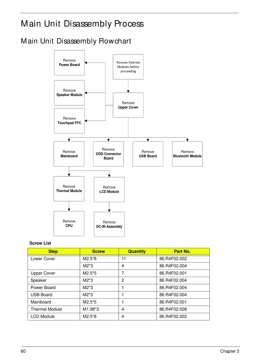
Main Screw List Quantity Part Number
External Modules Disassembly Flowchart
External Module Disassembly Process
Screw List Step Quantity
Removing the Battery Pack
Removing the SD Dummy Card
Removing the Keyboard
Chapter
Removing the ODD Module
Step Size Quantity Screw Type ODD Module M2.5*8
Step Size Quantity Screw Type ODD Bracket M2*3
Removing the Logic Lower Door
Step Size Quantity Screw Type
Removing the Dimm Module
Removing the Wlan Module
Step Size Quantity Screw Type Wlan Module M2*3
Detach the Wlan module from the Wlan socket
Removing the HDD Module
Step Size Quantity Screw Type HDD Carrier M3*3
Removing the RTC Battery
Main Unit Disassembly Process
Main Unit Disassembly Flowchart
Removing the Upper Cover
Chapter
Page
Step Size Quantity Screw Type Upper Cover M2.5*5
Removing the Speaker Module
Step Size Quantity Screw Type Upper Cover M2*3
Lift the speaker module clear of the device
Removing the Power Board
Step Size Quantity Screw Type Power Board M2*3
Chapter
Removing the Touchpad FFC
Removing the USB Board
Step Size Quantity Screw Type USB Board M2*3
Removing the Bluetooth Module
Removing the ODD Connector Board
Removing the Mainboard
Step Size Quantity Screw Type Mainboard M2.5*5
Chapter
Disconnect the Bluetooth cable from mainboard Chapter
Removing the Thermal Module
Removing the CPU
Removing the LCD Assembly
Step Size Quantity Screw Type LCD Assembly M2.5*8
Remove the LCD assembly from the lower cover
Removing the DC-IN Assembly
LCD Module Disassembly Process
LCD Module Disassembly Flowchart
Removing the LCD Bezel
Step Size Quantity Screw Type LCD Bezel M2.5*6
Removing the Camera Module
Removing the Inverter Board
Step Size Quantity Screw Type Inverter Board M2.5*5
Chapter
Removing the LCD/LED Panel
Step Size Quantity Screw Type LCD/LED Panel M2.5*5
Removing the LCD Brackets
Step Size Quantity Screw Type LCD Brackets M2*3
Removing the Lvds cable
Removing the Microphone Cable
Lift the microphone set clear of the panel Chapter
Removing the Antennas
Page
LCD Module Reassembly Procedure
Replacing the Antennas
Page
Replacing the Microphone Cable
Page
Replacing the Lvds Cable
Replacing the LCD Brackets
Replacing the LCD/LED Panel
Chapter 103
104 Chapter
Replacing the Camera Module
Replacing the LCD Bezel
Main Module Reassembly Procedure
Replacing the DC-IN Assembly
Replacing the LCD Assembly
Page
110 Chapter
Replacing the CPU
Replacing the Thermal Module
Connect the fan cable Chapter 113
Replacing the Mainboard
Chapter 115
116 Chapter
Replacing the ODD Connector Board
Replacing the Bluetooth Board
Replacing the USB Board
120 Chapter
Replacing the Touchpad FFC
Replacing the Power Board
Replacing the Speaker Module
Replacing the Upper Cover
Page
126 Chapter
Step Size Quantity Screw Type Upper Cover M2.5*5
Replacing the RTC Battery
Replacing the HDD Module
130 Chapter
Replacing the Wlan Module
Replacing the Dimm Modules
Replacing the Lower Logic Door
Replacing the ODD Module
Chapter 135
Replacing the Keyboard
Replacing the SD Dummy Card
Replacing the Battery
Common Problems
Symptoms Verified Go To
Power On Issue
Computer Shutsdown Intermittently
No Display Issue
No Post or Video
Random Loss of Bios Settings
Abnormal Video Display
LCD Failure
Built-In Keyboard Failure
Touchpad Failure
Internal Speaker Failure
Microphone Problems
Sound Problems
Select Set up microphone
Select Repair your computer
HDD Not Operating Correctly
Select Startup Repair
ODD Failure
ODD Not Operating Correctly
Discs Do Not Play
Drive Not Detected
Wireless Function Failure
Thermal Unit Failure
External Mouse Failure
Other Failures
Undetermined Problems
Intermittent Problems
Dimm
Post Code Range Phase
Post Codes
Peirecoverymedianotfound PEI
Peienterrecoverymode PEI
Peirecoverymediafound PEI
Peirecoveryloadfiledone PEI
Bdsentersetup BDS
Bdsenumerateallbootoption BDS
Bdsendofbootselection BDS
Bdsenterbootmanager BDS
Smmacpidisablestart SMM
Smmacpienablestart SMM
Smmacpienableend SMM
Smmacpidisableend SMM
Top View
Bottom View
LED1 ON/OFF LED LED4 LED2 HDD LED SW1
Power Board
LED3
USB/B Board
USB connector
ODD Connector
ODD Board
Steps for Clearing Bios Password Check
Clearing Password Check and Bios Recovery
Clearing Password Check
Clear Cmos Jumper
Bios Recovery Hotkey
Bios Recovery by Crisis Disk
Bios Recovery Boot Block
Steps for Bios Recovery from USB Storage
FRU Field Replaceable Unit List
Main Assembly
Aspire 5336 Exploded Diagrams
Description Acer Part No
Upper Assembly
LCD Assembly
LED Assembly
Aspire 5336 FRU List
Category Description Acer Part No
Foxconn Wireless LAN Broadcom 4312H
Liteon Wireless LAN Atheris HB97
BGN HM WN6603AH Foxconn Wireless LAN Atheros HB97
Power Cord US 3 PIN
Upper Case ASSY, INCL.TP UMA, Brown
Upper Case ASSY, INCL.TP UMA, Black
Upper Case ASSY, INCL.TP UMA, RED
Lower CASE-UMA
22A0RT0, ML320M,WD Sata 8MB LF F
22ZEST0, ML320S, 4K Drive Sata 8MB LF F/W
MK6465GSX,CAPRICORN BS,320G/P Sata 8MB LF F/WGJ002J
ODD SUPER-MULTI Drive Module
ODD Plds SUPER-MULTI Drive 12.7MM Tray
ANTENNA*2, CCD 1.3M, Black LCD Cover IMR-BLACK
ODD BEZEL-SM
Assy LCD Module 15.6W Wxga Glare W
LCD Bezel for W/CMOS
Ccfl LCD LPL 15.6W Wxga Glare
Ccfl LCD Samsung 15.6W Wxga Glare
ANTENNA*2, CCD 1.3M, Brown LCD Cover IMR-BROWN
ANTENNA*2, CCD 1.3M, RED LCD Cover IMR-RED
LED Cable for W/CMOS
Assy LED Module 15.6W Wxga Glare W
ANTENNA*2, CCD 1.3M, Black LED Cover IMR-BLACK
LED Bracket R&L
LED LCD LPL 15.6W Wxga Glare
LED LCD AUO 15.6W Wxga Glare
Saving LED LCD CMO 15.6W Wxga Glare N156B6
Color Engine LED LCD CPT 15.6W Wxga Glare
ANTENNA*2, CCD 1.3M, RED LED Cover IMR-RED
LCD Bezel for W/O Cmos
ANTENNA*2, W/O CCD, Black LCD Cover IMR-BLACK
LCD Cable for W/O Cmos
ANTENNA*2, W/O CCD, Brown LCD Cover IMR-BROWN
ANTENNA*2, W/O CCD, RED LCD Cover IMR-RED
ANTENNA*2, W/O CCD, Black LED Cover IMR-BLACK
LED Cable for W/O Cmos
ANTENNA*2, W/O CCD, Brown LED Cover IMR-BROWN
ANTENNA*2, W/O CCD, RED LED Cover IMR-RED
Memory Kingston SO-DIMM Ddriii
Mainboard AS5336 Intel GL40 V1.0 LF
Memory Elpida SO-DIMM Ddriii 1333 1GB
Memory Samsung SO-DIMM Ddriii
Speaker L
FAN-UMA
MIC SET-UMA
LCD Screw PAD
Screw 2.5D
Screw List
Screw 3.0D
Screw 2.0D
AS5336
Appendix a
Model Country Acer Part No Description
Appendix a
Appendix a 190
USA
Appendix a 192
AS5336-902G32Mncc W7HP64ASFR1 MC
Appendix a 194
AS5336 Spain LX.R4G02.032
Model Country Acer Part No
Memory
SO2GBIII10 SO1GBIII10
Appendix a 198
NLED15 SO2GBIII10
Appendix a 200
Extra Wireless Camera
SW1 LAN1
Appendix a 202
HDD 1GB
Appendix a 204
HDD 1GB
Appendix a 206
HDD 1GB
Appendix a 208
Test Compatible Components
Appendix B
Brand Type Description Acer Part No Adapter
Bluetooth
Microsoft Windows 7 Environment Test
Audio Codec
Intel
Brand Type Description Acer Part No
Card Reader
Hgst
Keyboard
Software
NB Chipset
SB Chipset
VGA Chip
Brand Type Description Acer Part No WiFi Antenna
Wireless LAN
Online Support Information
Appendix C
216
Index
218
Removing 55, 59
220