D.MIC_RET and OUT_RET are for HD audio panel only. You don’t need to connect them for AC’97 audio panel.
E.To activate the front mic.
For Windows® XP / XP
Select “Mixer”. Select “Recorder”. Then click “FrontMic”. For Windows® 7 / 7
Go to the "FrontMic" Tab in the Realtek Control panel. Adjust “Recording Volume”.
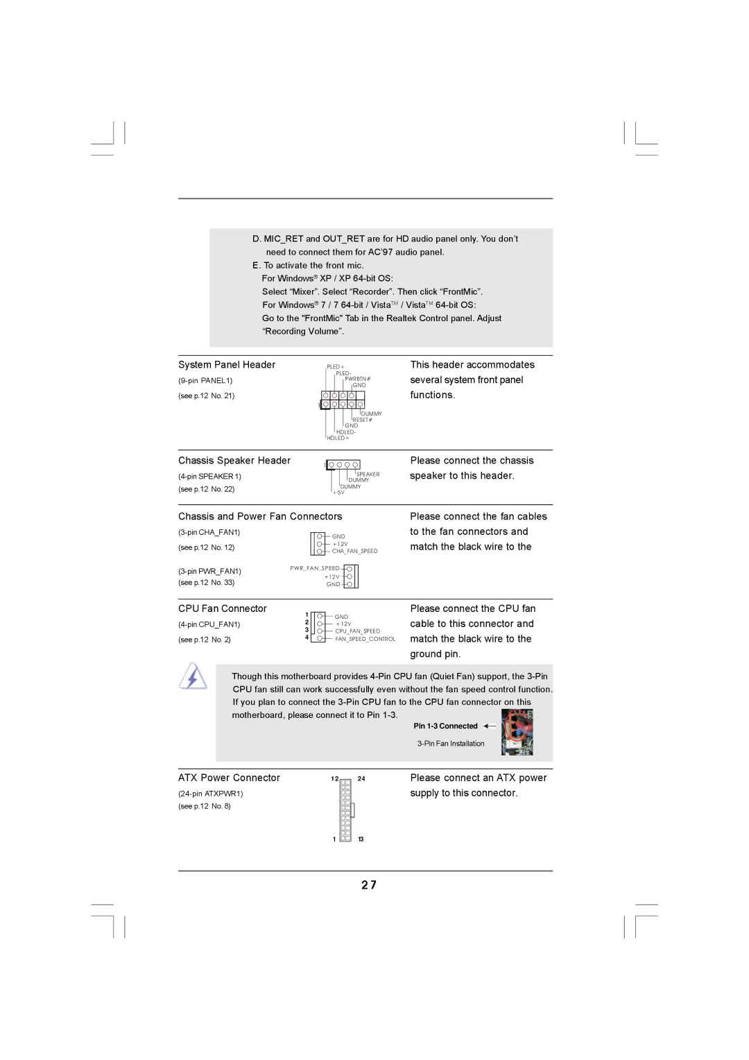
System Panel Header
(see p.12 No. 21)
1
PLED+
PLED-
PWRBTN#
GND
DUMMY RESET#
GND HDLED-
HDLED+
This header accommodates several system front panel functions.
Chassis Speaker Header
(see p.12 No. 22)
1
SPEAKER DUMMY
DUMMY +5V
Please connect the chassis speaker to this header.
Chassis and Power Fan Connectors
GND | |||
|
| ||
(see p.12 | No. 12) | +12V | |
CHA_FAN_SPEED | |||
|
| ||
PWR_FAN_SPEED | |||
+12V | |||
(see p.12 | No. 33) | ||
GND | |||
Please connect the fan cables to the fan connectors and match the black wire to the
CPU Fan Connector | 1 | GND | |
2 | +12V | ||
| 3 | CPU_FAN_SPEED | |
(see p.12 No. 2) | 4 | FAN_SPEED_CONTROL |
Please connect the CPU fan cable to this connector and match the black wire to the ground pin.
Though this motherboard provides
|
|
| Pin |
|
|
| |
|
|
|
|
ATX Power Connector | 12 | 24 | Please connect an ATX power |
|
| supply to this connector. | |
(see p.12 No. 8) |
|
|
|
| 1 | 13 |
|
2 7