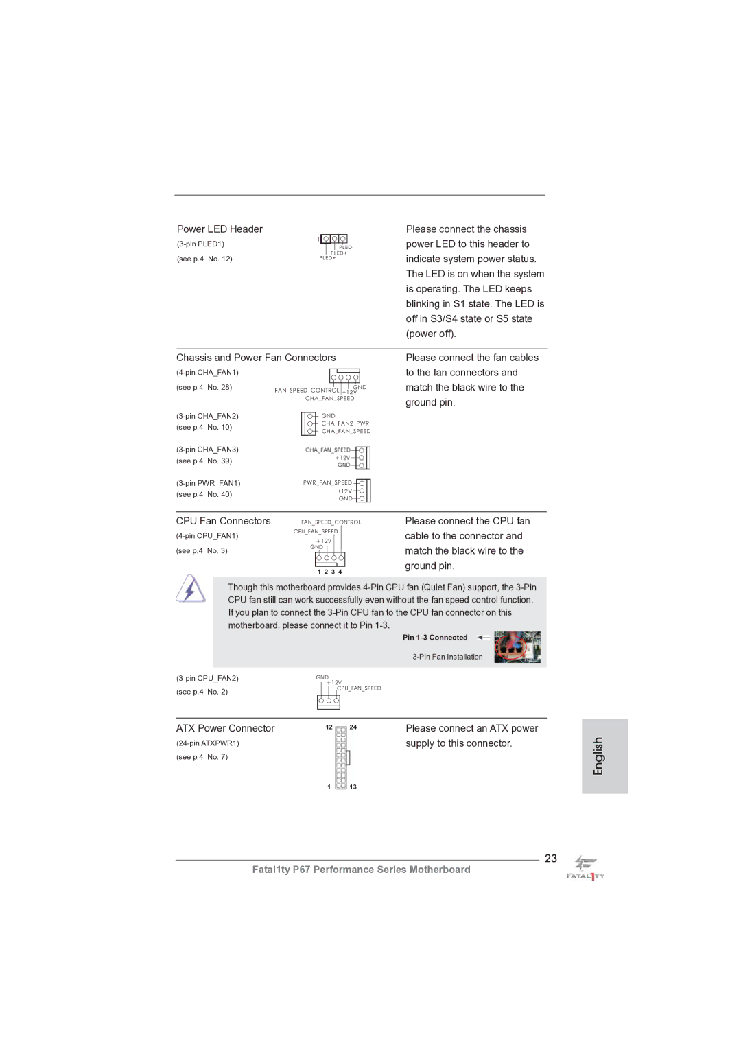
Power LED Header
1 |
|
|
|
|
|
| ||
|
|
|
|
| PLED- | |||
(see p.4 No. 12) |
|
|
| PLED+ | ||||
PLED+ | ||||||||
| ||||||||
Please connect the chassis power LED to this header to indicate system power status. The LED is on when the system is operating. The LED keeps blinking in S1 state. The LED is off in S3/S4 state or S5 state (power off).
Chassis and Power Fan Connectors
(see p.4 | No. 28) | FAN_SPEED_CONTROL +12V | |
|
| GND | |
|
| CHA_FAN_SPEED | |
GND | |||
(see p.4 | No. 10) | CHA_FAN2_PWR | |
CHA_FAN_SPEED | |||
|
| ||
Please connect the fan cables to the fan connectors and match the black wire to the ground pin.
| |||
(see p.4 | No. 39) |
| |
PWR_FAN_SPEED | |||
(see p.4 | No. 40) | +12V | |
GND | |||
|
| ||
CPU Fan Connectors | FAN_SPEED_CONTROL | Please connect the CPU fan | |
CPU_FAN_SPEED | cable to the connector and | ||
+12V | |||
|
| ||
(see p.4 No. 3) | GND | match the black wire to the | |
| |||
| 1 2 3 4 | ground pin. | |
|
|
Though this motherboard provides
Pin
GND | ||
| +12V | |
(see p.4 No. 2) | CPU_FAN_SPEED | |
|
| |
|
|
|
|
|
|
|
|
|
ATX Power Connector | 12 | 24 | Please connect an ATX power |
|
| supply to this connector. | |
(see p.4 No. 7) |
|
|
|
| 1 | 13 |
|
23