44
 EN
EN


USING

 THE
THE
 REMOTE
 CONTROL
 UNIT
UNIT

 (cont.)

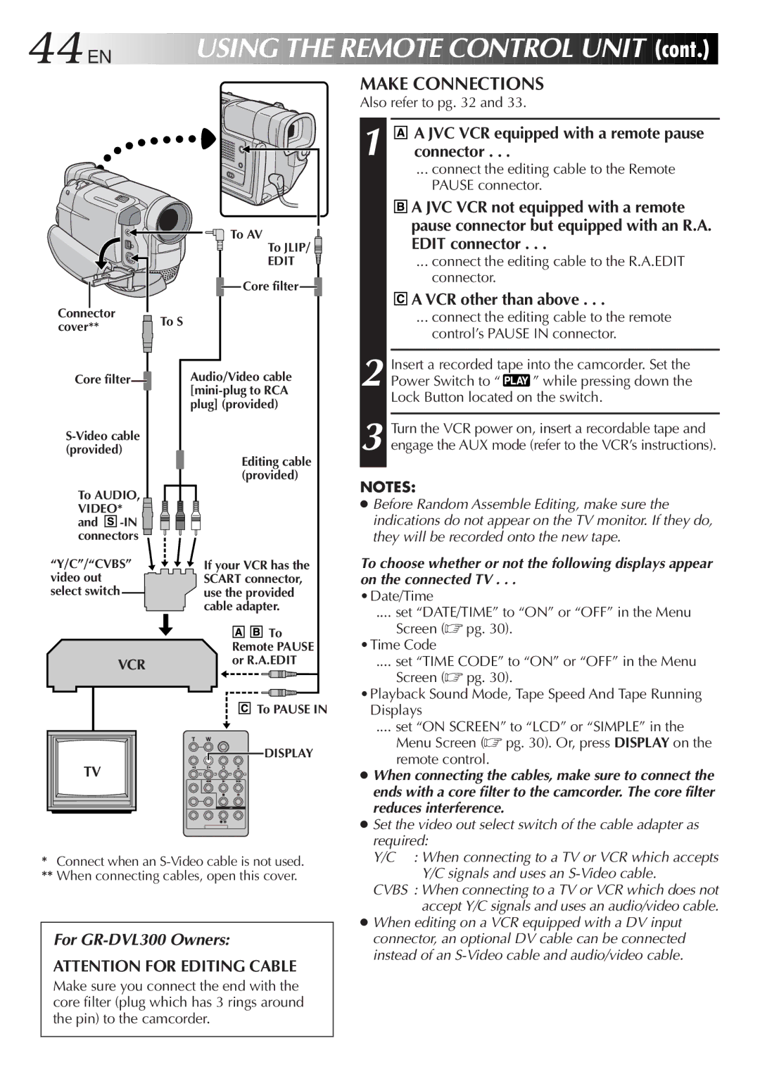
To AV
To JLIP/ ![]()
EDIT
![]() Core filter
Core filter![]()
Connector |
| To S | |
cover** |
| ||
|
| ||
|
|
|
|
|
|
|
|
MAKE CONNECTIONS
Also refer to pg. 32 and 33.
1![]() A JVC VCR equipped with a remote pause connector . . .
A JVC VCR equipped with a remote pause connector . . .
... connect the editing cable to the Remote PAUSE connector.
![]()
![]()
![]() A JVC VCR not equipped with a remote pause connector but equipped with an R.A. EDIT connector . . .
A JVC VCR not equipped with a remote pause connector but equipped with an R.A. EDIT connector . . .
... connect the editing cable to the R.A.EDIT connector.


 A VCR other than above . . .
... connect the editing cable to the remote control’s PAUSE IN connector.
Core filter![]()
To AUDIO, VIDEO* ![]() and
and ![]()
![]()
![]()
![]()
![]()
Audio/Video cable
Editing cable (provided)
2 Insert a recorded tape into the camcorder. Set the
Power Switch to “ ![]()
![]() ” while pressing down the Lock Button located on the switch.
” while pressing down the Lock Button located on the switch.
3 Turn the VCR power on, insert a recordable tape and engage the AUX mode (refer to the VCR’s instructions).
NOTES:
● Before Random Assemble Editing, make sure the |
indications do not appear on the TV monitor. If they do, |
they will be recorded onto the new tape. |
“Y/C”/“CVBS” video out select switch
VCR
If your VCR has the SCART connector, use the provided cable adapter.
![]()
![]()
![]()
![]()
![]() To Remote PAUSE or R.A.EDIT
To Remote PAUSE or R.A.EDIT
To choose whether or not the following displays appear on the connected TV . . .
•Date/Time
.... set “DATE/TIME” to “ON” or “OFF” in the Menu
Screen (☞ pg. 30). •Time Code
.... set “TIME CODE” to “ON” or “OFF” in the Menu
Screen (☞ pg. 30).
![]()
![]()
![]() To PAUSE IN
To PAUSE IN
DISPLAY
TV
*Connect when an
**When connecting cables, open this cover.
For GR-DVL300 Owners:
ATTENTION FOR EDITING CABLE
Make sure you connect the end with the core filter (plug which has 3 rings around the pin) to the camcorder.
•Playback Sound Mode, Tape Speed And Tape Running Displays
.... set “ON SCREEN” to “LCD” or “SIMPLE” in the
Menu Screen (☞ pg. 30). Or, press DISPLAY on the remote control.
●When connecting the cables, make sure to connect the ends with a core filter to the camcorder. The core filter reduces interference.
●Set the video out select switch of the cable adapter as required:
Y/C : When connecting to a TV or VCR which accepts Y/C signals and uses an
CVBS : When connecting to a TV or VCR which does not accept Y/C signals and uses an audio/video cable.
●When editing on a VCR equipped with a DV input connector, an optional DV cable can be connected instead of an