PT-L759VU, PT-L759XU specifications
The Panasonic PT-L759XU and PT-L759VU projectors are advanced projection solutions designed for a variety of settings, including educational institutions and corporate environments. These models stand out due to their impressive image quality, versatility, and user-friendly features.Both models utilize a powerful 3LCD technology, which ensures bright and vivid color reproduction while minimizing any potential color distortion associated with single-chip projectors. This results in sharp and natural images, making presentations, lectures, or video screenings exceptionally engaging. The projectors boast a brightness level of 7,000 lumens, making them suitable for environments with ample ambient light. This high brightness level allows content to be easily visible even in well-lit rooms, ensuring that audiences can see every detail.
In terms of resolution, the PT-L759XU and PT-L759VU feature a WXGA resolution of 1280 x 800 pixels, providing an excellent balance between image clarity and detailed presentations. This resolution supports a wide variety of content, including HD video and detailed slides, making it a perfect choice for multimedia presentations.
One of the standout features of these projectors is their advanced lens shift capability, which provides flexible placement options. Users can install the projector in different positions without compromising image quality or alignment. This is complemented by a powered zoom lens, which offers further flexibility, allowing users to easily adjust the projection size without moving the projector itself.
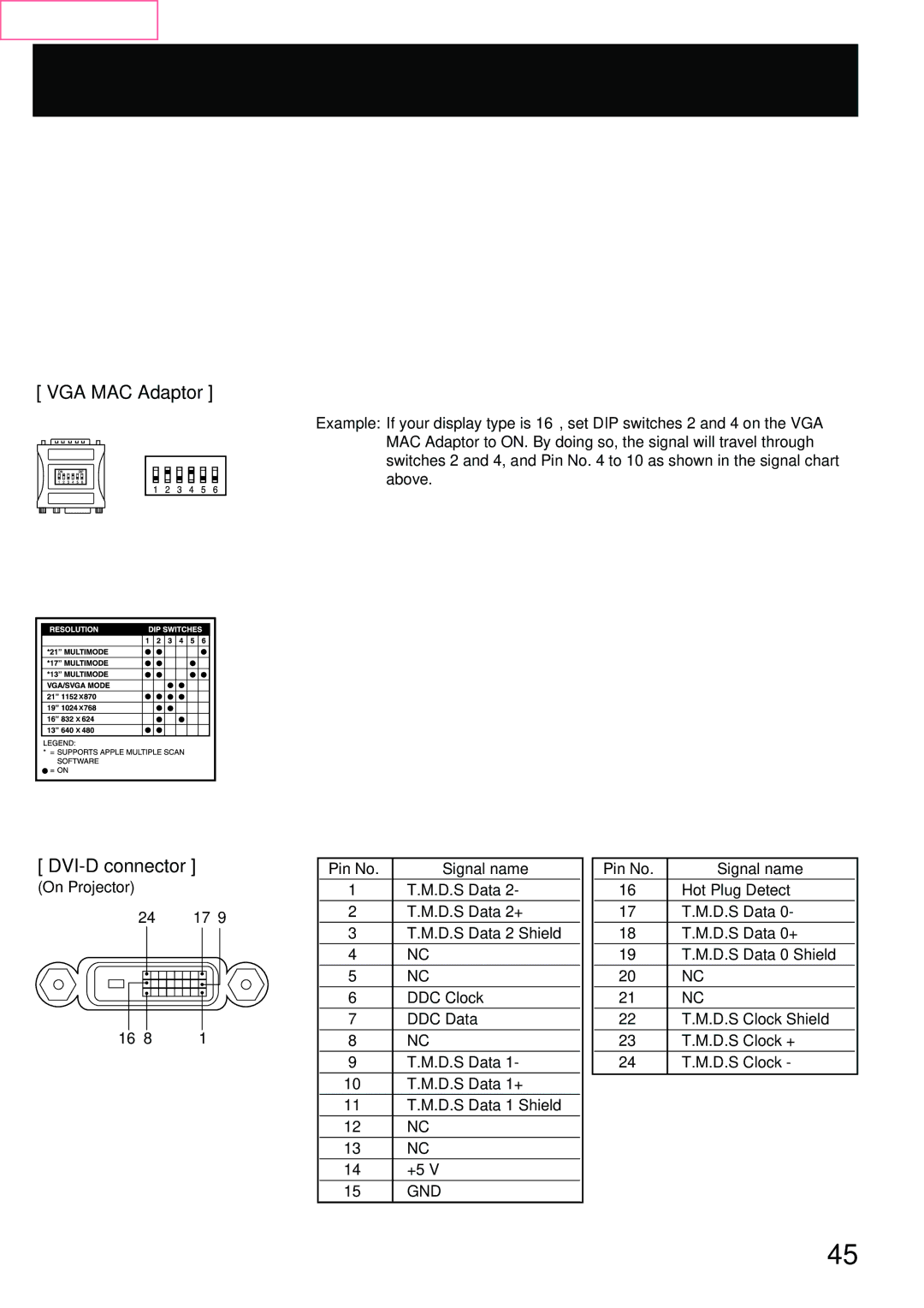
Both models are equipped with multiple connectivity options, including HDMI, VGA, and RCA inputs, ensuring compatibility with a wide range of devices. They also feature built-in network capabilities, allowing for easy integration into existing IT infrastructures and allowing for remote management. The projectors support Crestron, AMX, and PJLink protocols, making them ideal for modern smart classrooms and meeting rooms.
Energy efficiency is another notable characteristic of the PT-L759XU and PT-L759VU. With an Eco Mode, users can extend the lifespan of the lamp while reducing power consumption and maintenance costs.
In summary, the Panasonic PT-L759XU and PT-L759VU projectors deliver outstanding performance through vibrant image quality, versatile setup options, and user-friendly features. Their robust design and advanced technologies make them a reliable choice for any professional or educational setting.

