Fatal1ty Story
English
LIVIN’ Large
Copyright Notice
Disclaimer
Published June
Motherboard Layout
Panel
LAN Port LED Indications
Table for Audio Output Connection
English
Introduction
Package Contents
Specifications English
Supports D-Sub with max. resolution up to @ 75Hz
Audio
Rear Panel I/O
USB3.0
Connector
Smart Switch
Bios Feature
Monitor
Unique Feature
Support CD
Hardware
English
Transferring currently
English
Installation
Pre-installation Precautions
Screw Holes
Two orientation key notches
CPU Installation
Step Orient the CPU with the IHS Inte
Grated Heat Sink up. Locate Pin1
English
FAN2, see page 4. No.4
To the CPU fan connector on the motherboard
Step Place the heatsink onto the socket. Ensure
CPUFAN1, see page 4, No or CPU
Dual Channel Memory Configuration
Installation of Memory Modules Dimm
Break Notch
Installing a Dimm
Expansion Slots PCI Express Slots
Installing an expansion card
Requirements
Slitm and Quad Slitm Operation Guide
ASRock SLIBridge Card
Driver Installation and Setup
For Windows XP / XP 64-bit OS For Slitm mode only
Double-click Nvidia Settings icon on your Windows taskbar
Select Control Panel tab
Select Nvidia Control Panel tab
English
CrossFire Bridge
Installing Three CrossFireXTM-Ready Graphics Cards
CrossFireTM Bridge
ATI Catalyst Control Center
Install the required drivers to your system
For Windows XP OS
For Windows 7 / VistaTM OS
English
Dual Monitor and Surround Display Features
Dual Monitor Feature
Sub port DisplayPort DVI-D port
For Windows XP / XP 64-bit OS
Surround Display Feature
What is HDCP?
For Windows 7 / 7 64-bit / VistaTM / VistaTM 64-bit OS
Hdcp Function
ASRock Smart Remote Installation Guide
USB 2.0 header 9-pin, black CIR header 4-pin, gray
CIR sensors in different angles
Clear Cmos Jumper
Jumpers Setup
Jumper
Description
English
Onboard Headers and Connectors
One USB 3.0 header on this
USB 3.0 Header Besides four default USB
Optional wireless transmitting
Ports on the I/O panel, there is
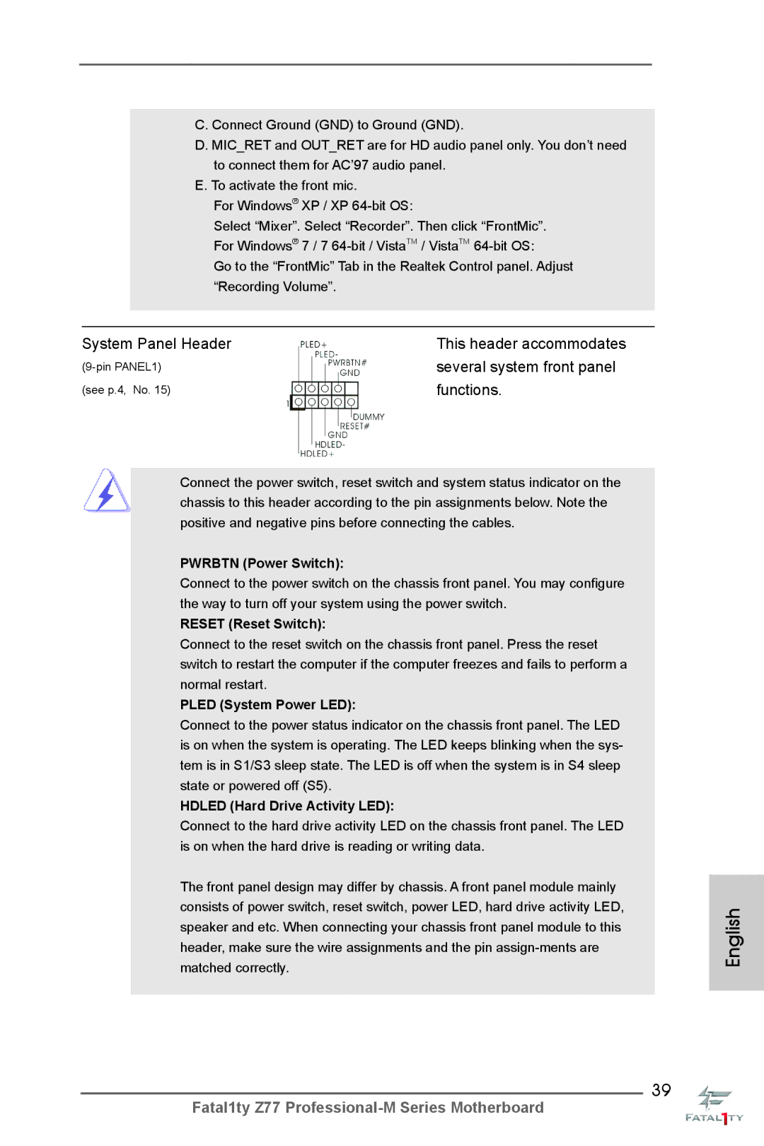
Several system front panel
System Panel Header
ATX Power Connector
CPU Fan Connectors Please connect the CPU fan
Cable to the connector
Match the black wire to
Serial port module
ATX 12V Power Connector Please connect an ATX
Clear the Cmos values
Smart Switches
Status Code Description
14 Dr. Debug
English
English
English
Install Windows XP / XP 64-bit OS on your system
Driver Installation Guide
Installing Windows XP / XP 64-bit Without RAID Functions
\ RAID Installation Guide
English
Software Support CD information
Bios Information
Einführung
Deutsch
Kartoninhalt
Spezifikationen
PS/2-Tastaturanschluss/Mausanschluss D-Sub port DVI-D port
Anschlüsse
Panel
An der Rückseite
Audioeingang / Lautsprecher vorne / Mikrofon
RJ-45 LAN Port mit LED ACT/LINK LED und Speed
Cmos löschen-Schalter mit LED
HD Audiobuchse Lautsprecher hinten / Mitte / Bass
Hardware Monitor
CD d’assistance
Einzigartige
Eigenschaft
Warnung
Zertifizierungen FCC, CE, Whql
Deutsch
Deutsch
Deutsch
Einstellung der Jumper
Jumper Einstellun Beschreibung
Cmos löschen
Für interne
Seriell-ATA2-Anschlüsse Diese vier Serial ATA2
SATA2-Verbínder
Unterstützten SATA-Datenkabel
Befindet sich ein USB
Serial ATA- Sata Stromversorgungskabel
USB 3.0-Header Neben vier Standard-USB
Ports am E/A-Panel
Anschluss für Audio auf
Consumer Infrared-Modul-Header Dieser Header kann zum
Anschließen Remote
Empfänger
Diesen Header an
Gehäuselautsprecher-Header Schließen Sie den
Systembetriebsstatus an
Betriebs-LED-Header Bitte schließen Sie die
Betriebs-LED des Gehäuses
Zur Anzeige des
Stromversorgung an
ATX-Netz-Header Verbinden Sie die ATX
Stromversorgung mit diesem
Header
Wird verwendet, um ein
COM-Anschlussmodul zu
Unterstützen
Schnell löschen können
Schnellschalter
Ein Schnellschalter, mit dem
Benutzer die CMOS-Werte
BIOS-Information
Français
Contenu du paquet
Spécifications
Panneau arrière
Supporte PXE
Connecteurs
USB
Unique
Interrupteur
Rapide
Caractéristique
Châssis, selon la température de l’unité centrale
Commande de ventilateur CPU/Châssis à plusieurs
Tachéomètre ventilateur processeur/châssis/pouvoir
Réglage automatique de la vitesse du ventilateur pour
Français
Français
Français
Réglage des cavaliers
Le cavalier Description
Effacer la Cmos
En-têtes et Connecteurs sur Carte
Il y a une barrette USB
Cordon d’alimentation Série ATA Sata
En-tête USB En plus des quatre ports USB
Par défaut sur le panneau
Système frontal
Reset Interrupteur de réinitialisation
Connecteur audio panneau
En-tête du panneau système Cet en-tête permet d’utiliser
Alimentazione del sistema. Il
En-tête
LED di accensione Collegare il LED di accensione
Chassi per indicare lo stato di
’alimentation électrique ATX
En-tête d’alimentation ATX Veuillez connecter l’unité
Tête
Connecteur ATX Veuillez connecter une unité
Un module de port COM
Interrupteur d’effacement de Cmos
Interrupteur de réinitialisation Rstbtn
Informations sur le Bios Informations sur le CD de support
Italiano
Contenuto della confezione
Specifiche
Posteriore I/O
Pannello
Rapido
Connettori
Interruttore
Interruttore pulizia Cmos con LED
Speciale
CD di
Supporto
Caratteristica
Attenzione
Italiano
Italiano
Setup dei Jumpers
Resettare la Cmos
Jumper Settaggio del Jumper
Serial ATA Sata
Connettori Serial ATA2
Cavi dati Serial ATA Sata
Cavo d’alimentazione
Di un header USB 3.0 che
Collettore USB
Standard del pannello I/O
Questa scheda madre è dotata
Pwrbtn interruttore d’alimentazione
Reset interruttore di ripristino
Collettore pannello di sistema
Diverse funzioni di sistema
Connettore ventolina CPU Collegare il cavo della ventolina
CPU a questo connettore e far
Combaciare il filo nero al pin
100
101
102
Interruttori rapidi
103
104
Introducción
Español
Contenido de la caja
105
Especificación
Panel Trasero
106
Admite la función Hdcp con puertos DVI, Hdmi y DisplayPort
Con puertos DVI, Hdmi y DisplayPort
Conexiones SATA2, admiten una velocidad de
107
En caliente los puertos SATA3A2 y eSATA3 son Compartidos
Conectores
Característica
108
Rápido
CD de soport
Certificaciones
109
110
111
112
Limpiar Cmos
Setup de Jumpers
Jumper Setting
113
114
115
116
Cabezal de panel de sistema
Sistema
117
Cabezal
118
Cabezal de alimentación ATX Conecte la fuente de
Alimentación ATX 12V a su
Se utiliza para admitir un
119
Conector de alimentaciónSLI/XFIRE
Cabezal del puerto COM Este cabezal del puerto COM
120
Conmutadores rápidos
121
Bios Información Información de Software Support CD
122
Введение
123
124
125
126
Осторожно
127
128
129
Перемычка Установка Описание
130
Не является направленным
Колодка USB
132
Reset кнопка сброса
133
Pwrbtn кнопка питания
Pled индикатор питания системы
134
135
Контакты 1-3 подключены
Наряду с Булавкой 1 и Прикрепите
136
Быстрое переключение
137
138
Информация о Bios
139
Introdução
Este pacote contém
Português
140
Português Especificações
Entrada/Saída
141
60Hz
Áudio
142
Interruptor
Inteligente
143
Aviso
144
145
146
147
Restaurar Cmos
Configuração dos Jumpers
JumperConfiguração
148
SATA2 / SATA3 quanto o
Conectores ATA3 Serial
Cabo de dados
Dados Sata pode ser
150
151
152
Com o pino de aterramento
153
Conector do ventilador da
CPU, coincidindo o fio preto
Um módulo de porta de série
154
Conector de força do ATX
Conector de porta de série Este conector COM1 suporta
155
Interruptores inteligentes
156
Informações da Bios Informações do CD de Suporte
157
Türkçe
Yuvası
158
Yonga seti
Bellek
159
Ses
Arka Panel
160
Sertifikalar
161
Donanım
Monitör
162
163
164
165
Jumper Ayar
CMOS’u temizleme
166
Kart üzerinde bir adet USB
USB 3.0 Fişleri Panelinde bulunan dört adet
Varsayılan USB 3.0 bağlantı
Noktasının yanı sıra, bu ana
Kasa Hoparlörü Fişi
168
Sistem Paneli Fişi
Işlevini barındırır
169
SLI/XFIRE Güç Konektörü Lütfen bir SLI/XFIRE güç
170
ATX 12V Güç Konektörü Lütfen bir ATX 12V güç
Kaynağını bu konektöre
Temizlemelerini sağlayan akıllı
171
Kullanıcıların hızlı bir şekilde
Cmos değerlerini
172
Bios Bilgileri Yazılım Destek CD’si bilgileri
173
제품소개
174
SATA3
175
176
177
178
179
180
점퍼세팅
181
Cmos 초기화
182
183
184
시스템 콘넥터
능을 지원하기 위한 것입니다
섀시 전원 LED 를 헤더에 연결
새시 스피커 헤더 새시 스피커를 이 헤더에 연결하
십시오
전원 LED 헤더 시스템 전원 상태를 표시하려면
186
리셋 스위치
187
Hdmispdif 헤더
전원 스위치
188
시스템 바이오스 정보 소프트웨어 지원 CD 정보
ASRock SLIBridge カード
189
Micro ATX フォームファクター 9.6-in x 9.6-in, 24.4 cm x 24.4 cm
シリアル l ATA Sata HDD 用電源変換ケーブル(オプション)
190
191
1080p Blu-ray BD / HD-DVD 再生サポート、DVI 、HDMI
クリア Cmos スイッヱ(LED 付き)x
192
193
194
ASRock XFast RAM は、F-Stream を含む新機能です。Windows オ
195
196
ASRock Crashless Bios を使って、ユーザーは失敗のおそれなく Bios
197
ジャンパ設定
オンボードのヘッダとコネクタ類。
198
されています。それぞれの USB
ントパネルの機能を提供します。
200
シャーシスピーカーヘッダ シャーシのスピーカーとこのヘッダを接
ATX パワーコネクタ
202
クイックスイッヱ
203
204
. ソフトウェア サポート CD 情報
一個華擎 SLIBridge 橋接卡
205
206
207
208
209
210
211
清除 Cmos
212
213
USB 3.0 擴展接頭
214
系統面板接頭
215
ATX 12V 接頭
216
CPU 風扇接頭
ATX 電源接頭
Hdmispdif 接頭,提供 Spdif
217
Cmos 中的數據。
218
Bios 信息
219
本主板支持各種微軟視窗操作系統:Microsoft Windows 7/7 64 位元 /VistaTM
220
電子信息產品污染控制標示
一張華擎 SLIBridge 卡
221
Micro ATX 規格 9.6 英吋 x 9.6 英吋 , 24.4 公分 x 24.4 公分
四條 Serial Atasata 數據線 選配
222
PS/2 鍵盤 / 滑鼠接口
223
DVI、HDMI 和 DisplayPort 接口支援 Hdcp 功能
HD-DVD 光碟
224
225
226
227
228
229
USB 3.0 擴充接頭
230
啟鍵等各種連線。
231
Pin ATX 電源安裝說明
232
ATX 12V 電源接口
233
234
Bios 訊息
235
本主板支援各種微軟 Windows 操作系統:Microsoft Windows 7/7 64 位元
Penjelasan
Isi Paket
236
237
Spesifikasi
Papan Belakang
238
Beralih
Ciri-ciri Bios
239
Penghubung
Penjaga
240
Sokongan CD
Fitur Unik
241
Installing OS on a HDD Larger Than 2TB in Ahci Mode
242
Installing OS on a HDD Larger Than 2TB in RAID Mode
Windows VistaTM 64-bit
243
244
Windows 7 64-bit
245