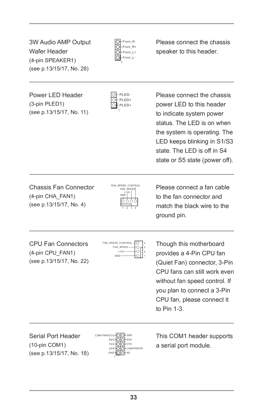
3W Audio AMP Output Wafer Header
Front_R-
Front_R+
Front_L+
![]() Front_L-
Front_L-
1
Please connect the chassis speaker to this header.
Power LED Header
(see p.13/15/17, No. 11)
![]() PLED-
PLED-
![]() PLED+
PLED+
![]() PLED+
PLED+
1
Please connect the chassis power LED to this header to indicate system power status. The LED is on when the system is operating. The LED keeps blinking in S1/S3 state. The LED is off in S4 state or S5 state (power off).
Chassis Fan Connector
FAN_SPEED_CONTROL
FAN_SPEED
+12V GND
1 2 3 4
Please connect a fan cable to the fan connector and match the black wire to the ground pin.
CPU Fan Connectors
FAN_SPEED_CONTROL 4
FAN_SPEED3
+12V2
GND1
Though this motherboard provides a
Serial Port Header
(see p.13/15/17, No. 18)
COM PWR/DCD | DSR |
RXD | RTS |
TXD | CTS |
DTR | COM PWR/RI |
GND | NC |
1 |
|
This COM1 header supports a serial port module.
33