2.4 Onboard Headers and Connectors
Onboard headers and connectors are NOT jumpers. Do NOT place jumper caps over these headers and connectors. Plac- ing jumper caps over the headers and connectors will cause permanent damage to the motherboard!
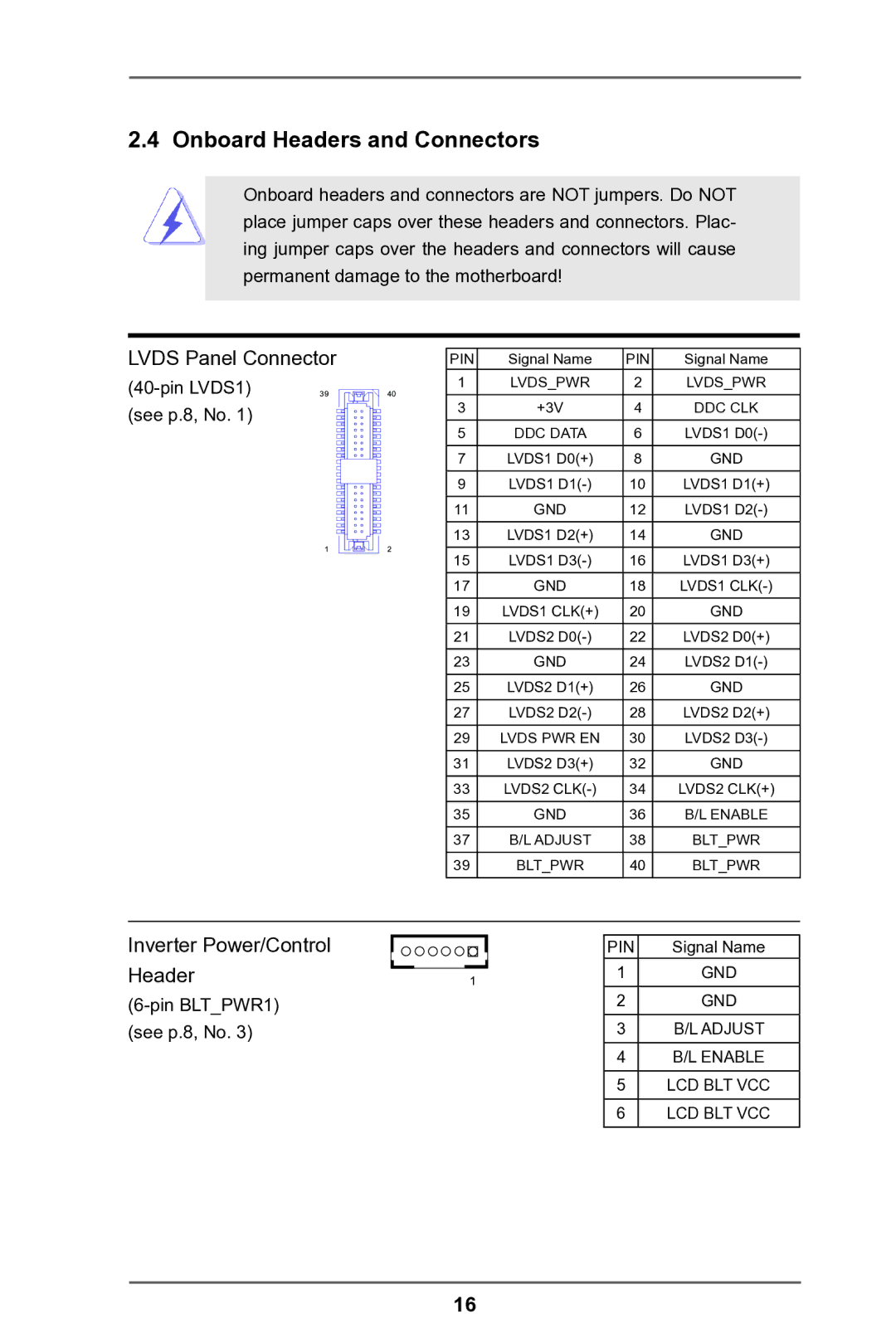
LVDS Panel Connector
| 39 | 40 |
(see p.8, No. 1) |
|
|
12
PIN | Signal Name | PIN | Signal Name |
1 | LVDS_PWR | 2 | LVDS_PWR |
3 | +3V | 4 | DDC CLK |
5 | DDC DATA | 6 | LVDS1 |
7 | LVDS1 D0(+) | 8 | GND |
9 | LVDS1 | 10 | LVDS1 D1(+) |
11 | GND | 12 | LVDS1 |
13 | LVDS1 D2(+) | 14 | GND |
15 | LVDS1 | 16 | LVDS1 D3(+) |
17 | GND | 18 | LVDS1 |
19 | LVDS1 CLK(+) | 20 | GND |
21 | LVDS2 | 22 | LVDS2 D0(+) |
23 | GND | 24 | LVDS2 |
25 | LVDS2 D1(+) | 26 | GND |
27 | LVDS2 | 28 | LVDS2 D2(+) |
29 | LVDS PWR EN | 30 | LVDS2 |
31 | LVDS2 D3(+) | 32 | GND |
33 | LVDS2 | 34 | LVDS2 CLK(+) |
35 | GND | 36 | B/L ENABLE |
37 | B/L ADJUST | 38 | BLT_PWR |
39 | BLT_PWR | 40 | BLT_PWR |
Inverter Power/Control Header
|
|
|
| PIN | Signal Name |
|
|
|
| ||
1 |
| 1 | GND | ||
|
|
| |||
|
|
|
| 2 | GND |
|
|
|
|
|
|
|
|
|
| 3 | B/L ADJUST |
|
|
|
| 4 | B/L ENABLE |
|
|
|
|
|
|
|
|
|
| 5 | LCD BLT VCC |
|
|
|
| 6 | LCD BLT VCC |
16