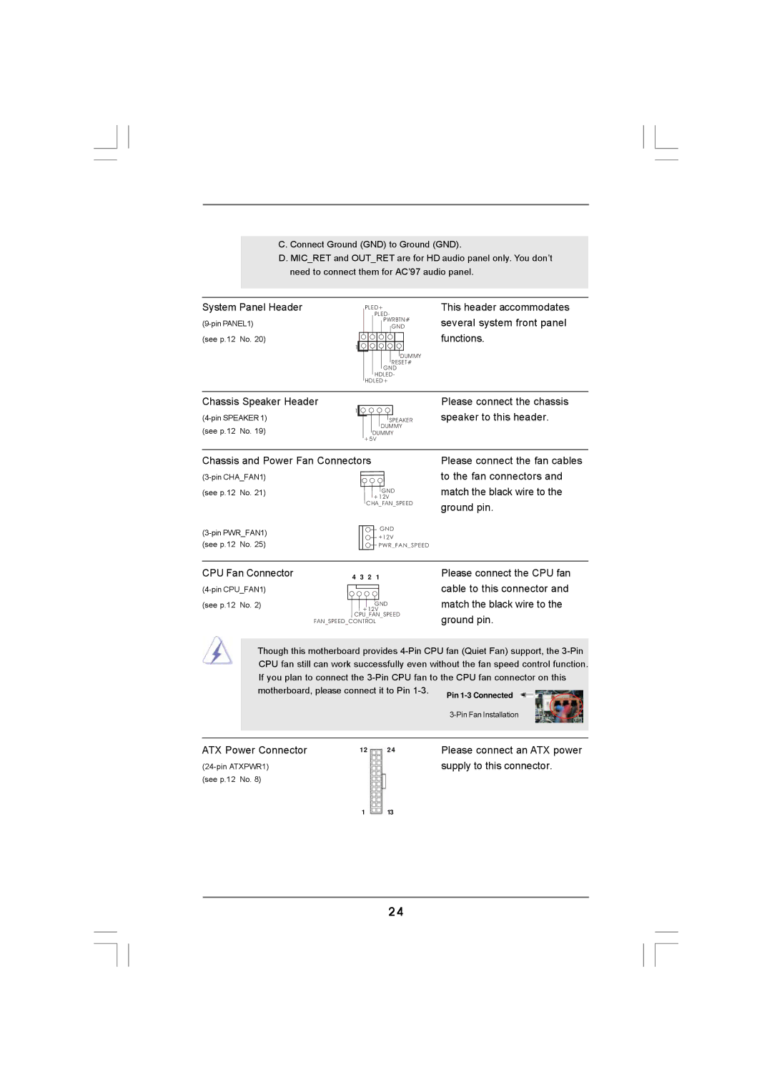
Please connect an ATX power supply to this connector.
Though this motherboard provides 4-Pin CPU fan (Quiet Fan) support, the 3-Pin CPU fan still can work successfully even without the fan speed control function. If you plan to connect the 3-Pin CPU fan to the CPU fan connector on this motherboard, please connect it to Pin 1-3. Pin 1-3 Connected
FAN_SPEED_CONTROL
This header accommodates several system front panel functions.
Please connect the chassis speaker to this header.
Please connect the fan cables to the fan connectors and match the black wire to the ground pin.
Please connect the CPU fan cable to this connector and match the black wire to the ground pin.
C. Connect Ground (GND) to Ground (GND).
D.MIC_RET and OUT_RET are for HD audio panel only. You don’t need to connect them for AC’97 audio panel.
System Panel Header
(see p.12 No. 20)
1
PLED+
PLED-
PWRBTN#
GND
DUMMY RESET#
GND HDLED-
HDLED+
Chassis Speaker Header
1
(see p.12 No. 19)
SPEAKER DUMMY
DUMMY +5V
Chassis and Power Fan Connectors
| |||
(see p.12 | No. 21) | GND | |
|
| +12V | |
|
| CHA_FAN_SPEED | |
GND | |||
+12V | |||
(see p.12 | No. 25) | ||
PWR_FAN_SPEED | |||
|
| ||
CPU Fan Connector | 4 3 2 1 | ||
| |||
(see p.12 | No. 2) | GND | |
|
| +12V | |
|
| CPU_FAN_SPEED | |
|
|
| |
|
|
| |
|
|
| |
ATX Power Connector | 12 | 24 |
(see p.12 No. 8)
1 13
24