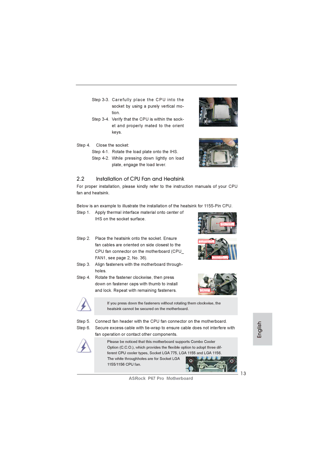
Step
Step
Step 4. Close the socket:
Step
plate, engage the load lever.
2.2Installation of CPU Fan and Heatsink
For proper installation, please kindly refer to the instruction manuals of your CPU fan and heatsink.
Below is an example to illustrate the installation of the heatsink for
IHS on the socket surface.
Apply Thermal
Interface Material
Step 2. Place the heatsink onto the socket. Ensure fan cables are oriented on side closest to the CPU fan connector on the motherboard (CPU_ FAN1, see page 2, No. 36).
Step 3. Align fasteners with the motherboard through- holes.
Step 4. Rotate the fastener clockwise, then press down on fastener caps with thumb to install and lock. Repeat with remaining fasteners.
Fan cables on side closest to MB header
Fastener slots pointing straight out
Press Down
(4 Places)
If you press down the fasteners without rotating them clockwise, the heatsink cannot be secured on the motherboard.
Step 5. Connect fan header with the CPU fan connector on the motherboard. Step 6. Secure excess cable with
fan operation or contact other components.
Please be noticed that this motherboard supports Combo Cooler Option (C.C.O.), which provides the flexible option to adopt three dif- ferent CPU cooler types, Socket LGA 775, LGA 1155 and LGA 1156. The white throughholes are for Socket LGA
1155/1156 CPU fan.
13
English
ASRock P67 Pro Motherboard