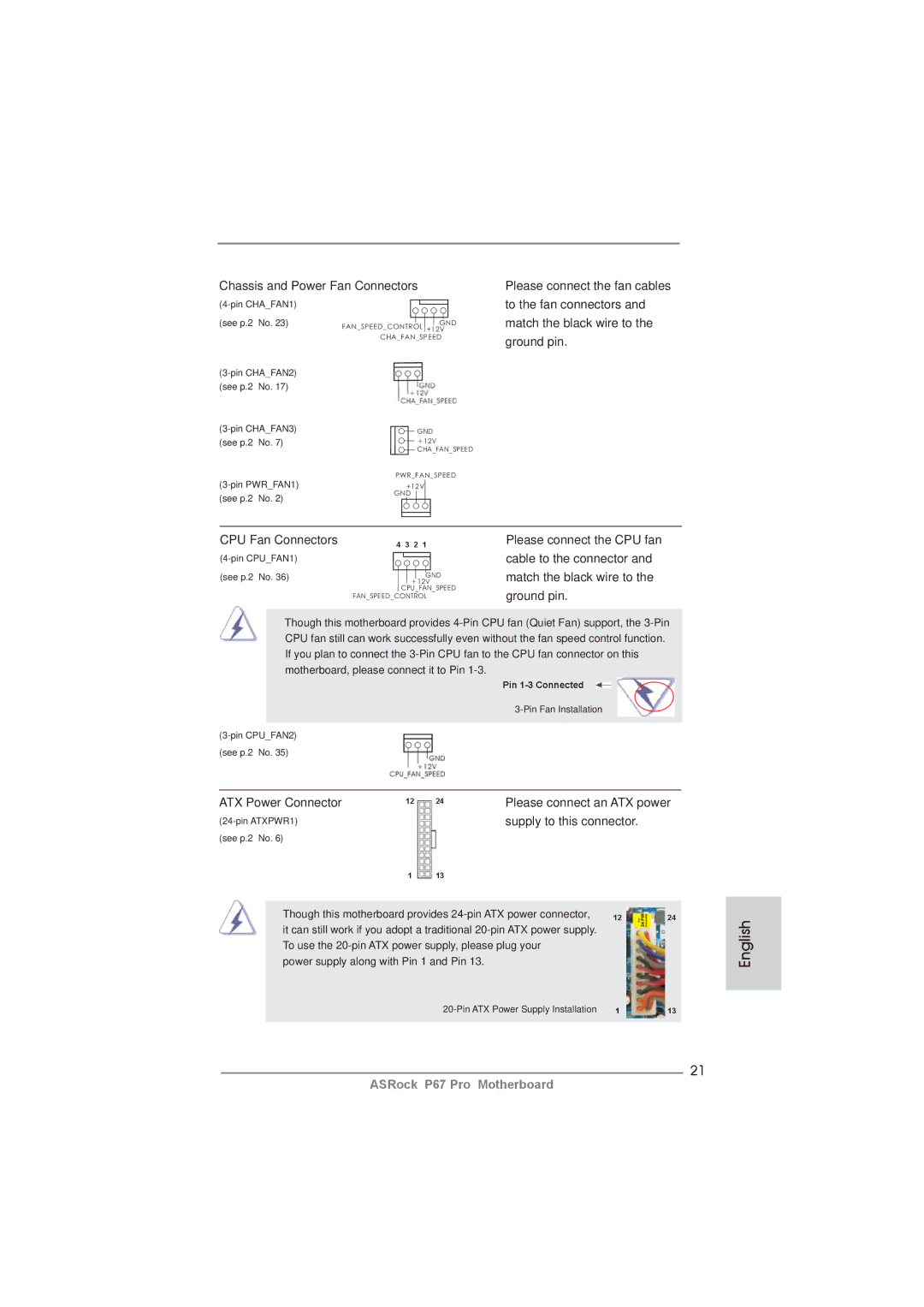
Chassis and Power Fan Connectors
(see p.2 | No. 23) | FAN_SPEED_CONTROL +12V |
|
| GND |
|
| CHA_FAN_SPEED |
| ||
(see p.2 | No. 17) |
|
GND | ||
(see p.2 | No. 7) | +12V |
|
| |
|
| CHA_FAN_SPEED |
PWR_FAN_SPEED | ||
+12V | ||
(see p.2 | No. 2) | GND |
| ||
Please connect the fan cables to the fan connectors and match the black wire to the ground pin.
CPU Fan Connectors | 4 3 2 1 | Please connect the CPU fan |
| cable to the connector and | |
(see p.2 No. 36) | +12V | match the black wire to the |
| GND |
|
| CPU_FAN_SPEED | ground pin. |
| FAN_SPEED_CONTROL | |
|
|
Though this motherboard provides
Pin
(see p.2 No. 35)
ATX Power Connector | 12 | 24 | Please connect an ATX power | ||||
|
| supply to this connector. |
| ||||
(see p.2 No. 6) |
|
|
|
|
|
| |
|
| 1 | 13 |
|
|
|
|
|
|
|
|
| |||
| Though this motherboard provides | 12 |
| 24 | |||
|
| ||||||
| it can still work if you adopt a traditional |
|
|
| |||
| To use the |
|
|
| |||
| power supply along with Pin 1 and Pin 13. |
|
|
|
| ||
|
|
| 1 |
| 13 | ||
|
|
|
|
|
|
|
|
21
English
ASRock P67 Pro Motherboard