ASRock Z87 Extreme6 manual ATX Power Connector Pin ATXPWR1 See p.11 or p.12, No

Models: Z87 Extreme6

1 115
Download 115 pages 60.89 Kb
Page 37
Image 37

Z87 Extreme6/ac / Z87 Extreme6
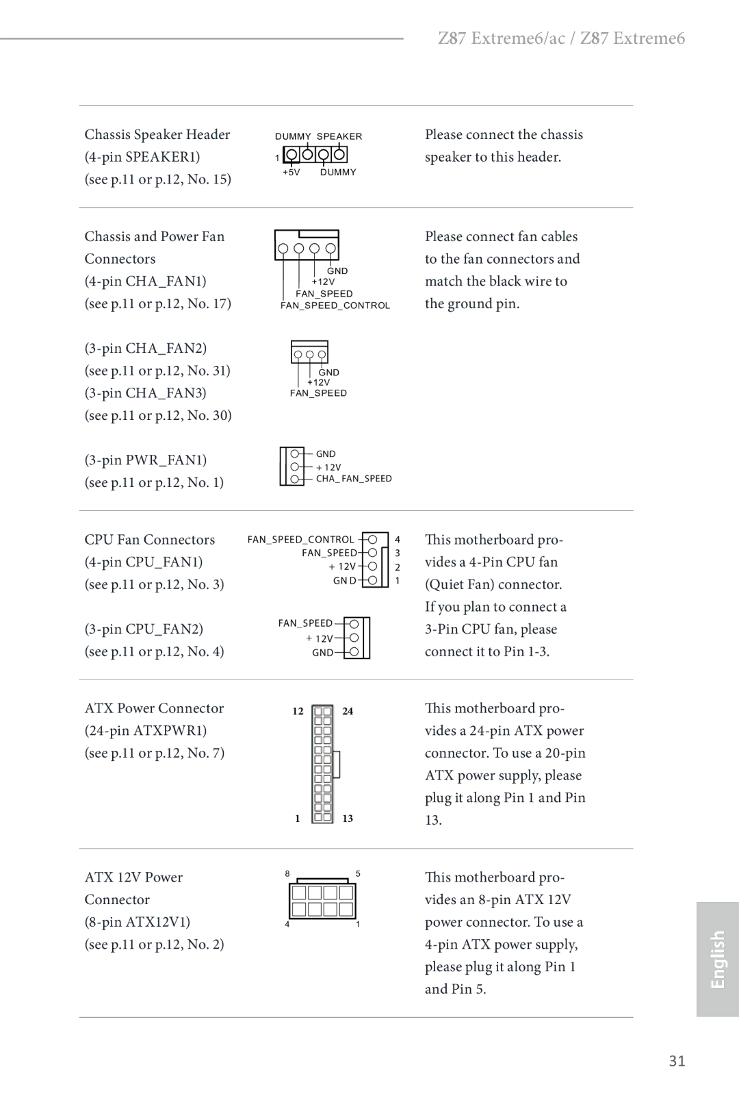
Chassis Speaker Header

DUMMY SPEAKER

Please connect the chassis

(4-pin SPEAKER1)

1


speaker to this header.

(see p.11 or p.12, No. 15)


+5V DUMMY


Chassis and Power Fan Connectors

(4-pin CHA_FAN1) (see p.11 or p.12, No. 17)

(3-pin CHA_FAN2) (see p.11 or p.12, No. 31) (3-pin CHA_FAN3) (see p.11 or p.12, No. 30)

(3-pin PWR_FAN1) (see p.11 or p.12, No. 1)

GND

+12V FAN_SPEED

FAN_SPEED_CONTROL

GND +12V

FAN_SPEED

GND

+ 12V

CHA_ FAN_SPEED

Please connect fan cables to the fan connectors and match the black wire to the ground pin.

CPU Fan Connectors (4-pin CPU_FAN1) (see p.11 or p.12, No. 3)

(3-pin CPU_FAN2) (see p.11 or p.12, No. 4)

FAN_SPEED_CONTROL

4

FAN_SPEED

3

+ 12V

2

GN D

1

FAN_SPEED

+12V GND

This motherboard pro- vides a 4-Pin CPU fan (Quiet Fan) connector. If you plan to connect a 3-Pin CPU fan, please connect it to Pin 1-3.

ATX Power Connector

12

24

(24-pin ATXPWR1)


(see p.11 or p.12, No. 7)


1

13

This motherboard pro- vides a 24-pin ATX power connector. To use a 20-pin ATX power supply, please plug it along Pin 1 and Pin 13.

ATX 12V Power Connector (8-pin ATX12V1)

(see p.11 or p.12, No. 2)

8

4

5

1

This motherboard pro- vides an 8-pin ATX 12V power connector. To use a 4-pin ATX power supply, please plug it along Pin 1 and Pin 5.

English

31

Page 37
Image 37
ASRock Z87 Extreme6 manual ATX Power Connector Pin ATXPWR1 See p.11 or p.12, No