Rev. A.1, 10/99

Page- 8

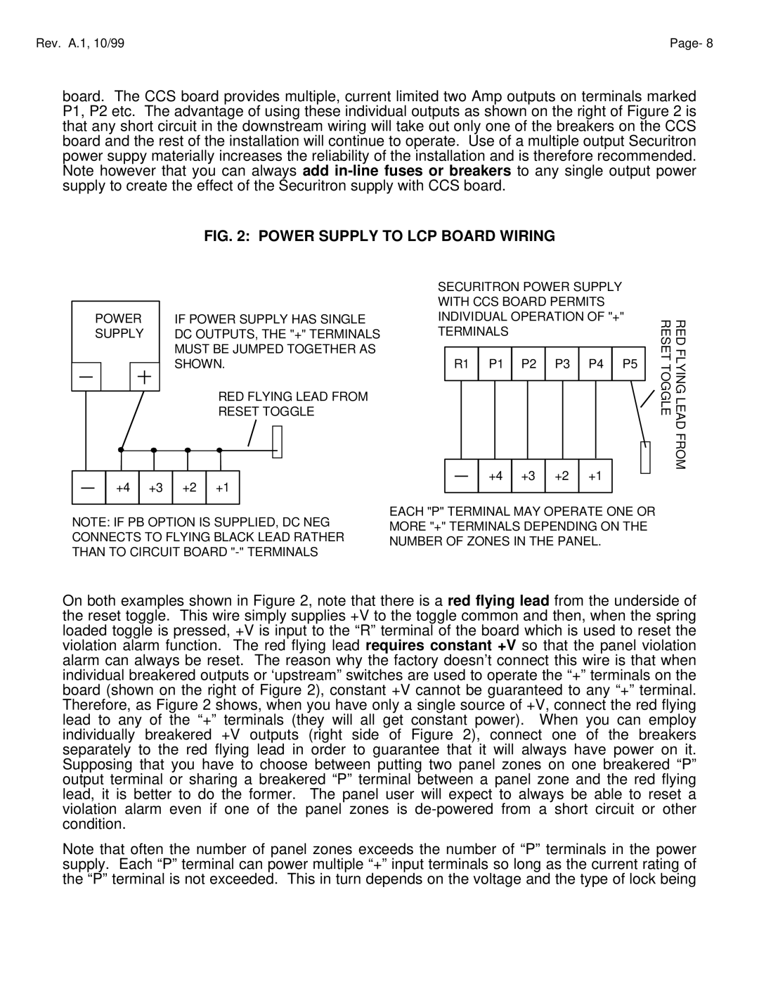
board. The CCS board provides multiple, current limited two Amp outputs on terminals marked P1, P2 etc. The advantage of using these individual outputs as shown on the right of Figure 2 is that any short circuit in the downstream wiring will take out only one of the breakers on the CCS board and the rest of the installation will continue to operate. Use of a multiple output Securitron power suppy materially increases the reliability of the installation and is therefore recommended. Note however that you can always add in-line fuses or breakers to any single output power supply to create the effect of the Securitron supply with CCS board.

FIG. 2: POWER SUPPLY TO LCP BOARD WIRING


POWER

IF POWER SUPPLY HAS SINGLE


SUPPLY

DC OUTPUTS, THE "+" TERMINALS


MUST BE JUMPED TOGETHER AS


SHOWN.


RED FLYING LEAD FROM


RESET TOGGLE


+4 +3 +2 +1

NOTE: IF PB OPTION IS SUPPLIED, DC NEG CONNECTS TO FLYING BLACK LEAD RATHER THAN TO CIRCUIT BOARD "-" TERMINALS

SECURITRON POWER SUPPLY

WITH CCS BOARD PERMITS

INDIVIDUAL OPERATION OF "+"

TERMINALS

R1 P1 P2 P3 P4 P5

+4 +3 +2 +1

EACH "P" TERMINAL MAY OPERATE ONE OR MORE "+" TERMINALS DEPENDING ON THE NUMBER OF ZONES IN THE PANEL.

RED FLYING LEAD FROM RESET TOGGLE

On both examples shown in Figure 2, note that there is a red flying lead from the underside of the reset toggle. This wire simply supplies +V to the toggle common and then, when the spring loaded toggle is pressed, +V is input to the “R” terminal of the board which is used to reset the violation alarm function. The red flying lead requires constant +V so that the panel violation alarm can always be reset. The reason why the factory doesn’t connect this wire is that when individual breakered outputs or ‘upstream” switches are used to operate the “+” terminals on the board (shown on the right of Figure 2), constant +V cannot be guaranteed to any “+” terminal. Therefore, as Figure 2 shows, when you have only a single source of +V, connect the red flying lead to any of the “+” terminals (they will all get constant power). When you can employ individually breakered +V outputs (right side of Figure 2), connect one of the breakers separately to the red flying lead in order to guarantee that it will always have power on it. Supposing that you have to choose between putting two panel zones on one breakered “P” output terminal or sharing a breakered “P” terminal between a panel zone and the red flying lead, it is better to do the former. The panel user will expect to always be able to reset a violation alarm even if one of the panel zones is de-powered from a short circuit or other condition.

Note that often the number of panel zones exceeds the number of “P” terminals in the power supply. Each “P” terminal can power multiple “+” input terminals so long as the current rating of the “P” terminal is not exceeded. This in turn depends on the voltage and the type of lock being

Page 10
Image 10
Assa ELECTRIC LOCK manual Power Supply to LCP Board Wiring

ELECTRIC LOCK specifications

Assa Electric Lock is a cutting-edge security solution designed to address the evolving needs of modern access control systems. Utilizing advanced technologies, this lock integrates both traditional locking mechanisms with state-of-the-art electronic features, providing an unparalleled level of security for residential and commercial properties.

One of the standout features of the Assa Electric Lock is its ability to incorporate various access modes. Users can choose between key-based entry, key fob access, and mobile app control. This versatility ensures that users can select the most convenient method for their specific needs while still maintaining robust security. The inclusion of a mobile application elevates user control, allowing for remote access management and real-time monitoring of lock status.

The lock is engineered with robust materials, ensuring durability and resistance to tampering. It features a high-quality housing that can withstand environmental elements, making it suitable for both indoor and outdoor installations. The Assa Electric Lock is also designed to function seamlessly with existing security systems, providing compatibility without compromising overall security.

Assa Electric Lock employs advanced encryption technologies to safeguard user data and access control commands. With encryption protocols in place, users can be confident that their security information is protected from unauthorized access. The lock also includes an audit trail feature, which logs entry and exit events, allowing property owners to track access history easily.

In addition to its electronic capabilities, Assa Electric Lock prioritizes user-friendly design. The intuitive interface and installation process make it accessible to both professional installers and DIY enthusiasts. Furthermore, the lock is equipped with a backup key option, ensuring that users can always access their property in the event of a power failure or technical issues.

The lock's energy efficiency is another key characteristic, as it operates on low power consumption without sacrificing performance. This commitment to sustainability not only reduces costs but also minimizes the environmental impact.

Overall, the Assa Electric Lock stands out in the evolving landscape of security technology. It combines traditional reliability with modern electronic features, making it an ideal choice for those seeking enhanced security solutions. With its range of access options, robust materials, advanced encryption, and user-friendly design, the Assa Electric Lock is leading the way in secure access control.