ELECTRIC LOCK specifications
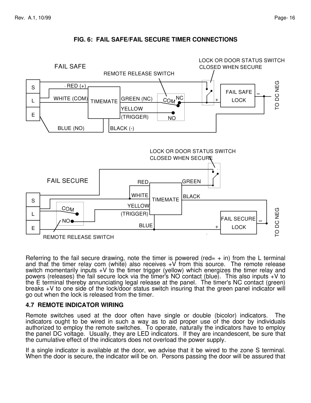
Assa Electric Lock is a cutting-edge security solution designed to address the evolving needs of modern access control systems. Utilizing advanced technologies, this lock integrates both traditional locking mechanisms with state-of-the-art electronic features, providing an unparalleled level of security for residential and commercial properties.One of the standout features of the Assa Electric Lock is its ability to incorporate various access modes. Users can choose between key-based entry, key fob access, and mobile app control. This versatility ensures that users can select the most convenient method for their specific needs while still maintaining robust security. The inclusion of a mobile application elevates user control, allowing for remote access management and real-time monitoring of lock status.
The lock is engineered with robust materials, ensuring durability and resistance to tampering. It features a high-quality housing that can withstand environmental elements, making it suitable for both indoor and outdoor installations. The Assa Electric Lock is also designed to function seamlessly with existing security systems, providing compatibility without compromising overall security.
Assa Electric Lock employs advanced encryption technologies to safeguard user data and access control commands. With encryption protocols in place, users can be confident that their security information is protected from unauthorized access. The lock also includes an audit trail feature, which logs entry and exit events, allowing property owners to track access history easily.
In addition to its electronic capabilities, Assa Electric Lock prioritizes user-friendly design. The intuitive interface and installation process make it accessible to both professional installers and DIY enthusiasts. Furthermore, the lock is equipped with a backup key option, ensuring that users can always access their property in the event of a power failure or technical issues.
The lock's energy efficiency is another key characteristic, as it operates on low power consumption without sacrificing performance. This commitment to sustainability not only reduces costs but also minimizes the environmental impact.
Overall, the Assa Electric Lock stands out in the evolving landscape of security technology. It combines traditional reliability with modern electronic features, making it an ideal choice for those seeking enhanced security solutions. With its range of access options, robust materials, advanced encryption, and user-friendly design, the Assa Electric Lock is leading the way in secure access control.

