EXPLOSION. TO REDUCE RISK OF A SPARK NEAR BATTERY:
a.Position ac and dc cords to reduce risk of damage by hood, door, or moving engine part.
b.Stay clear of fan blades, belts, pulleys, and other parts that can cause injury to persons.
c.Check polarity of battery posts. POSITIVE (POS, P, +) battery post usually has larger diameter than NEGATIVE (NEG, N,
d.Determine which post of battery is grounded (connected) to the chassis. If negative post is grounded to chassis (as in most vehicles), see item "e". If positive post is grounded to the chassis, see item "f".
e.For
f.For
g.When disconnecting charger, turn switches to off, disconnect AC cord, remove clip from vehicle chassis, and then remove clip from battery terminal.
h.See operating instructions for length of charge information.
18.FOLLOW THESE STEPS WHEN BATTERY IS OUTSIDE VEHICLE. A SPARK NEAR THE BATTERY MAY CAUSE BATTERY EXPLOSION. TO REDUCE RISK OF A SPARK NEAR BATTERY:
a.Check polarity of battery posts. POSITIVE (POS, P, +) battery post usually has a larger diameter than NEGATIVE (NEG, N,
b.Attach at least a
c.Connect POSITIVE (RED) charger clip to POSITIVE (POS, P, +) post of battery.
d.Position yourself and free end of cable as far away from battery as possible - then connect NEGATIVE (BLACK) charger clip to free end of cable.
e.Do not face battery when making final connection.
f.When disconnecting charger, always do so in reverse sequence of connecting procedure and break the first connection while as far away from battery as practicle.
g.A marine (boat) battery must be removed and charged on shore. To charge it on board requires equipment specially designed for marine use.
19.GROUNDING AND AC POWER CORD CONNECTION INSTRUCTIONS
Charger should be grounded to reduce risk of electric shock. Charger is equipped with an electric cord having an equipment grounding conductor and a grounding plug. The plug must be plugged into an outlet that is properly installed and grounded in accordance with all local codes and ordinances.
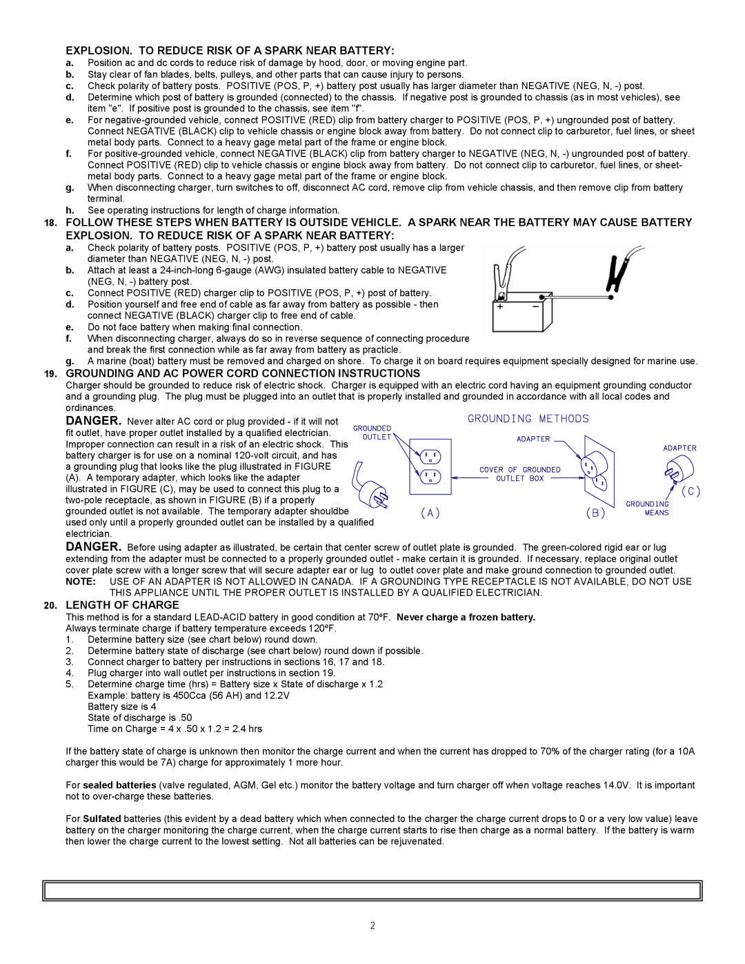
DANGER. Never alter AC cord or plug provided - if it will not fit outlet, have proper outlet installed by a qualified electrician. Improper connection can result in a risk of an electric shock. This battery charger is for use on a nominal
agrounding plug that looks like the plug illustrated in FIGURE
(A). A temporary adapter, which looks like the adapter illustrated in FIGURE (C), may be used to connect this plug to a
used only until a properly grounded outlet can be installed by a qualified electrician.
DANGER. Before using adapter as illustrated, be certain that center screw of outlet plate is grounded. The
NOTE: USE OF AN ADAPTER IS NOT ALLOWED IN CANADA. IF A GROUNDING TYPE RECEPTACLE IS NOT AVAILABLE, DO NOT USE THIS APPLIANCE UNTIL THE PROPER OUTLET IS INSTALLED BY A QUALIFIED ELECTRICIAN.
20.LENGTH OF CHARGE
This method is for a standard
1.Determine battery size (see chart below) round down.
2.Determine battery state of discharge (see chart below) round down if possible.
3.Connect charger to battery per instructions in sections 16, 17 and 18.
4.Plug charger into wall outlet per instructions in section 19.
5.Determine charge time (hrs) = Battery size x State of discharge x 1.2 Example: battery is 450Cca (56 AH) and 12.2V
Battery size is 4
State of discharge is .50
Time on Charge = 4 x .50 x 1.2 = 2.4 hrs
If the battery state of charge is unknown then monitor the charge current and when the current has dropped to 70% of the charger rating (for a 10A charger this would be 7A) charge for approximately 1 more hour.
For sealed batteries (valve regulated, AGM, Gel etc.) monitor the battery voltage and turn charger off when voltage reaches 14.0V. It is important not to
For Sulfated batteries (this evident by a dead battery which when connected to the charger the charge current drops to 0 or a very low value) leave battery on the charger monitoring the charge current, when the charge current starts to rise then charge as a normal battery. If the battery is warm then lower the charge current to the lowest setting. Not all batteries can be rejuvenated.
2