Memory System
SETUP H/W .3
3.HARDWARE SETUP
3.5.1Memory Installation
WARNING! Make sure that you unplug your power supply when adding or removing memory modules or other system components. Failure to do so may cause severe damage to both your motherboard and expansion cards
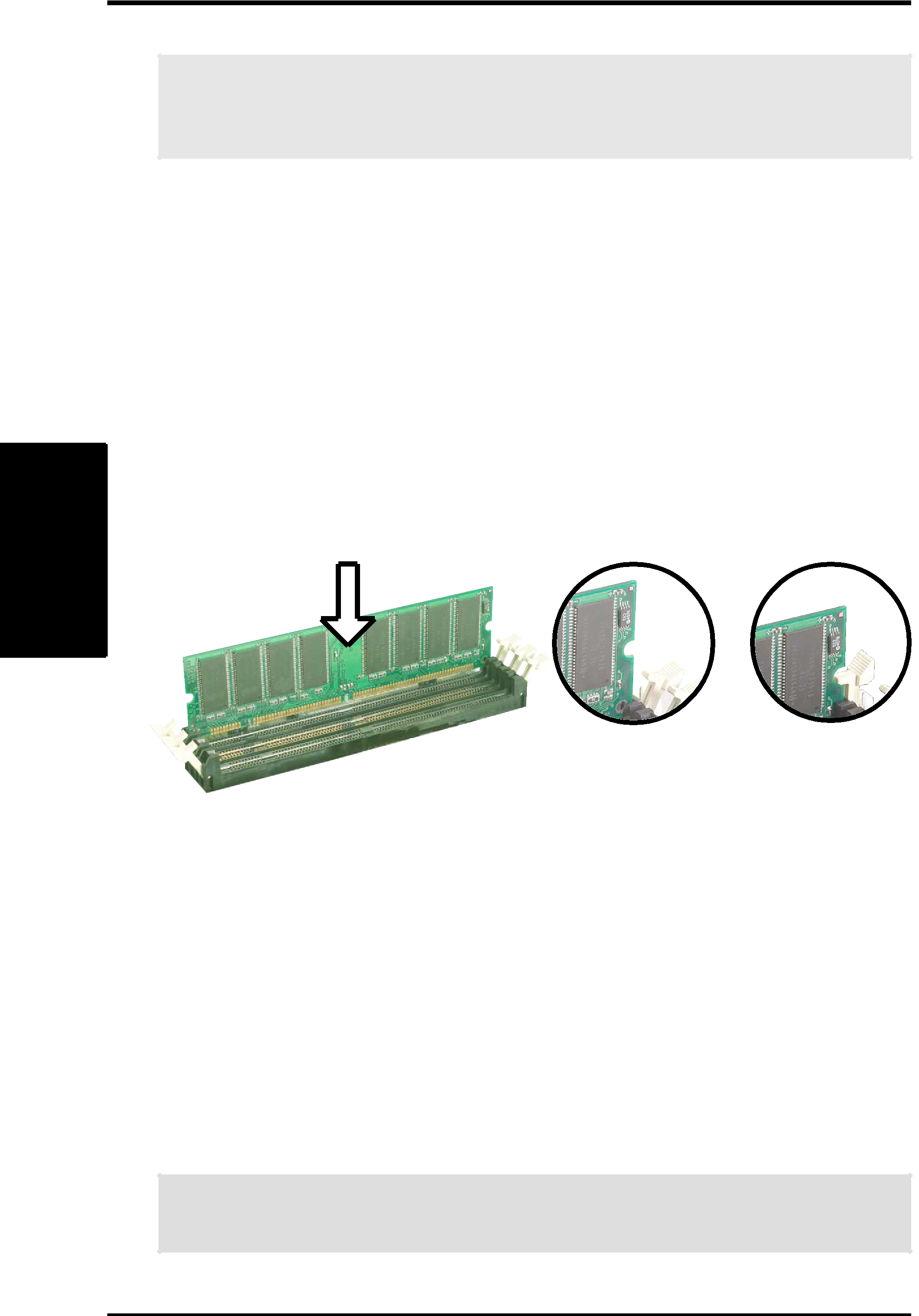
Insert the module(s) as shown. Because the number of pins are different on either side of the breaks, the module will only fit in the orientation shown. A
Installing a DIMM:
1.Unlock a DIMM socket by pressing the retaining clips outward.
2.Align a DIMM on the socket such that the notches on the DIMM exactly match the notches in the socket.
3.Firmly insert the DIMM into the socket until the retaining clips snap back in place.
Unlocked Retaining Clip | Locked Retaining Clip |
3.5.2 General DIMM Memo
•DIMMs that have more than 18 chips are not supported on this motherboard.•For the system CPU bus to operate at 200 MHz/266MHz, use only•ASUS motherboards support SPD (Serial Presence Detect) DIMMs. This is the memory of choice for best performance vs. stability.
•
•Please refer to Appendix 7.1 for a list of Qualified Vendors for DIMMs that have been tested for use with the
WARNING! Be sure that the DIMMs you use can handle the specified DDR SDRAM MHz or else bootup will not be possible.
22 | ASUS |