1.2Motherboard overview
1.2.1Motherboard layout
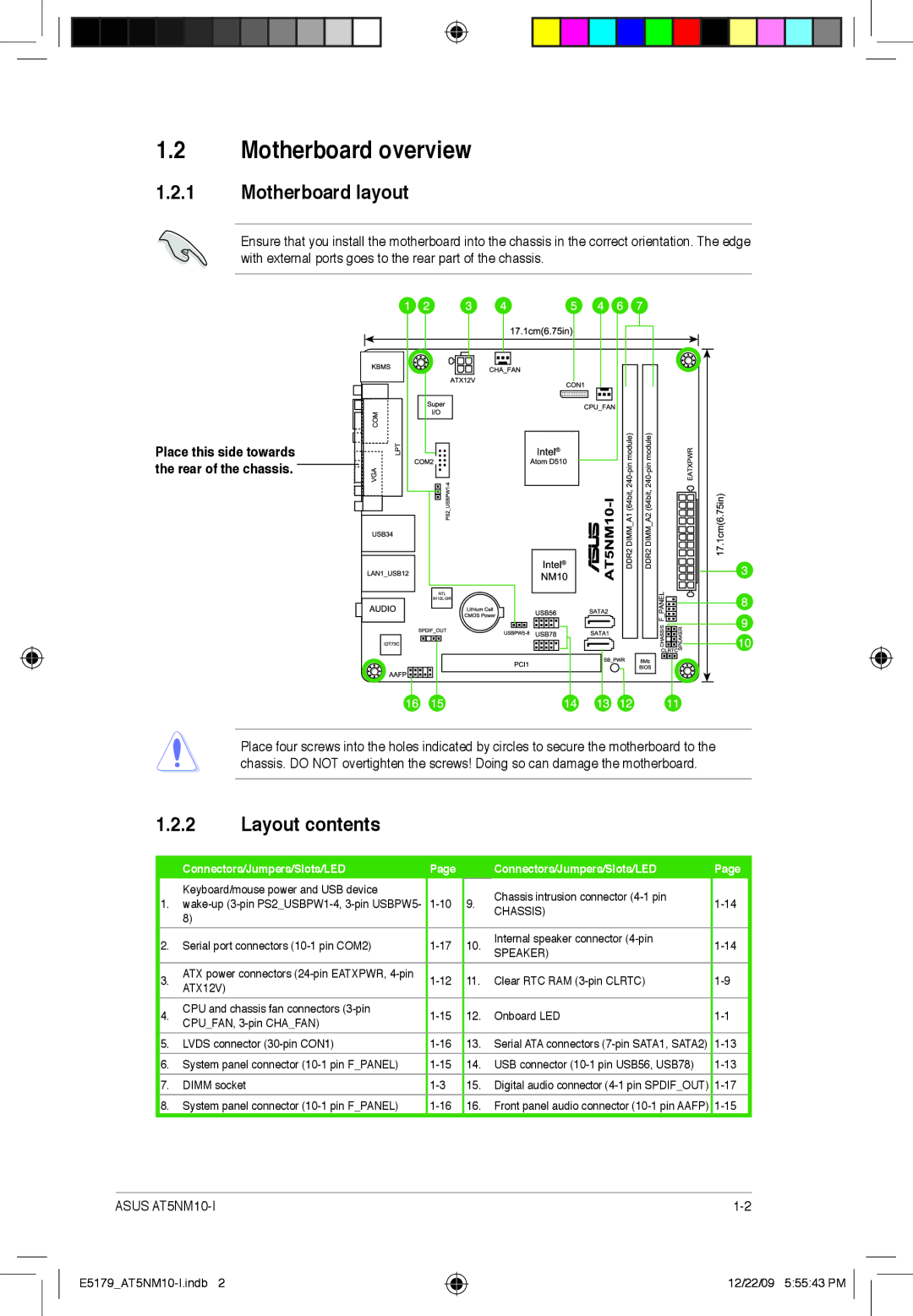
Ensure that you install the motherboard into the chassis in the correct orientation. The edge with external ports goes to the rear part of the chassis.
Place this side towards |
the rear of the chassis. |
Place four screws into the holes indicated by circles to secure the motherboard to the chassis. DO NOT overtighten the screws! Doing so can damage the motherboard.
1.2.2Layout contents
| Connectors/Jumpers/Slots/LED | Page |
| Connectors/Jumpers/Slots/LED | |
| Keyboard/mouse power and USB device |
|
| Chassis intrusion connector | |
1. | 9. | ||||
CHASSIS) | |||||
8) |
|
| |||
|
|
| |||
Page
| 2. | Serial port connectors | 10. | Internal speaker connector |
| ||
| SPEAKER) |
| |||||
|
|
|
|
|
|
| |
| 3. | ATX power connectors | 11. | Clear RTC RAM |
| ||
| ATX12V) |
| |||||
|
|
|
|
|
|
| |
| 4. | CPU and chassis fan connectors | 12. | Onboard LED |
| ||
| CPU_FAN, |
| |||||
|
|
|
|
|
|
| |
| 5. | LVDS connector | 13. | Serial ATA connectors |
| ||
| 6. | System panel connector | 14. | USB connector |
| ||
| 7. | DIMM socket | 15. | Digital audio connector |
| ||
| 8. | System panel connector | 16. | Front panel audio connector |
|
ASUS |
12/22/09 5:55:43 PM