7.USB 2.0 ports 3 and 4. These two
8.USB 2.0 ports 1 and 2. These two
9.VGA port. This
10.Serial![]() connector. This
connector. This
11.PS/2 keyboard port (purple). This port is for a PS/2 keyboard.
1.10.2 Internal
 connectors
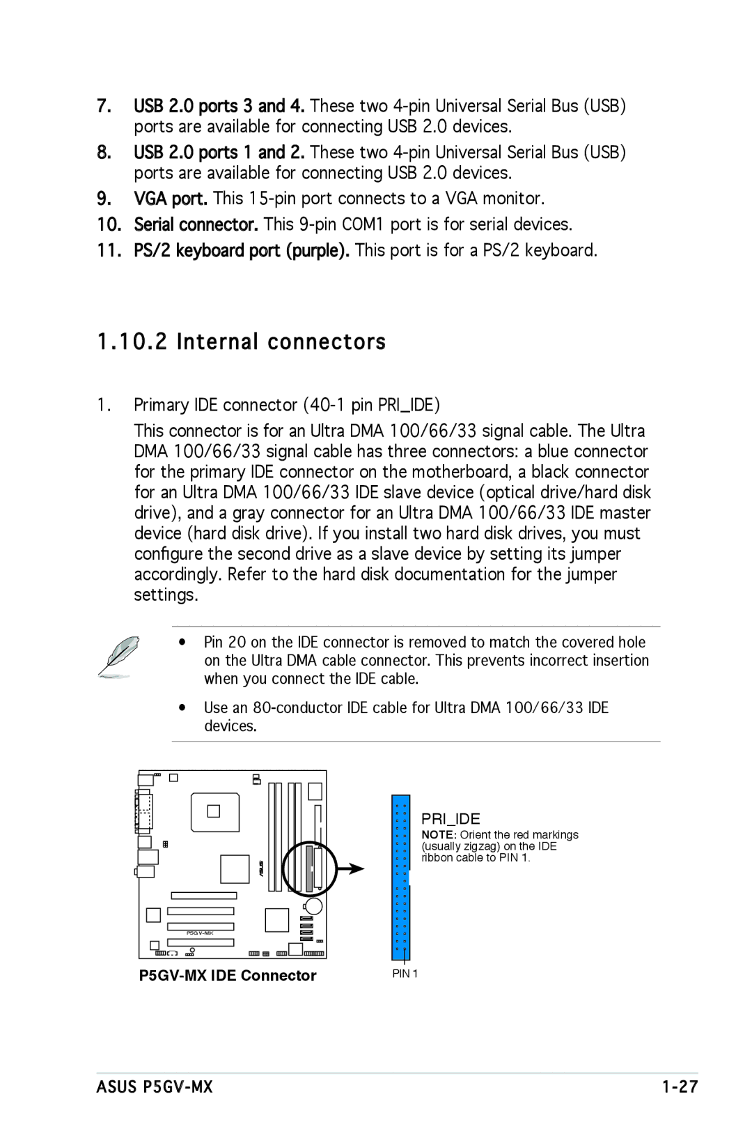
1.Primary IDE connector
This connector is for an Ultra DMA 100/66/33 signal cable. The Ultra DMA 100/66/33 signal cable has three connectors: a blue connector for the primary IDE connector on the motherboard, a black connector for an Ultra DMA 100/66/33 IDE slave device (optical drive/hard disk drive), and a gray connector for an Ultra DMA 100/66/33 IDE master device (hard disk drive). If you install two hard disk drives, you must configure the second drive as a slave device by setting its jumper accordingly. Refer to the hard disk documentation for the jumper settings.
• Pin 20 on the IDE connector is removed to match the covered hole on the Ultra DMA cable connector. This prevents incorrect insertion when you connect the IDE cable.
•Use an
PRI_IDE
NOTE: Orient the red markings (usually zigzag) on the IDE ribbon cable to PIN 1.
| PIN 1 |
ASUS |