Chapter 5: Advanced Serverboard Setup
Floppy Connector
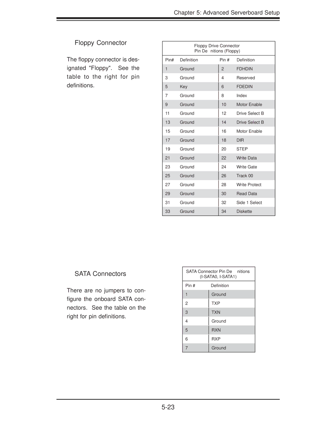
Floppy Drive Connector
Pin Definitions (Floppy)
The fl oppy connector is des- ignated "Floppy". See the table to the right for pin defi nitions.
Pin# Defi nition
1Ground
3Ground
5Key
7Ground
9Ground
11 Ground
13Ground
15Ground
17Ground
19Ground
21Ground
23Ground
25Ground
27Ground
29Ground
31 Ground
33 Ground
Pin # Defi nition
2FDHDIN
4Reserved
6FDEDIN
8Index
10Motor Enable
12Drive Select B
14Drive Select B
16Motor Enable
18DIR
20STEP
22Write Data
24Write Gate
26Track 00
28Write Protect
30Read Data
32 Side 1 Select
34 Diskette
SATA Connectors
There are no jumpers to con-
figure the onboard SATA con- nectors. See the table on the right for pin defi nitions.
SATA Connector Pin Definitions
Pin # | Defi nition |
1Ground
2TXP
3TXN
4Ground
5RXN
6RXP
7Ground