SUPER MICRO Computer 6014L-M manual Speaker/Power LED/Keylock, Wake-On-Ring, Wake-On-LAN

Models: 6014L-M

1 120
Download 120 pages 53.25 Kb
Page 52
Image 52
Speaker/Power LED/Keylock

SUPERSERVER 6014L-M User's Manual

Speaker/Power LED/Keylock

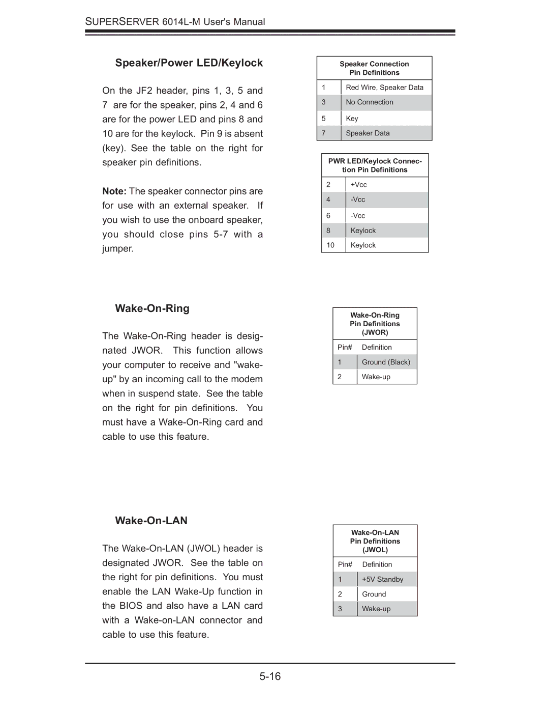
On the JF2 header, pins 1, 3, 5 and

7are for the speaker, pins 2, 4 and 6 are for the power LED and pins 8 and 10 are for the keylock. Pin 9 is absent (key). See the table on the right for speaker pin defi nitions.

Note: The speaker connector pins are for use with an external speaker. If you wish to use the onboard speaker, you should close pins 5-7 with a jumper.

Speaker Connection

Pin Definitions

1Red Wire, Speaker Data

3No Connection

5Key

7Speaker Data

PWR LED/Keylock Connec-

tion Pin Definitions

2+Vcc

4-Vcc

6-Vcc

8Keylock

10 Keylock

Wake-On-Ring

The Wake-On-Ring header is desig- nated JWOR. This function allows your computer to receive and "wake- up" by an incoming call to the modem when in suspend state. See the table on the right for pin defi nitions. You must have a Wake-On-Ring card and cable to use this feature.

Wake-On-Ring

Pin Definitions

(JWOR)

Pin# Defi nition

1Ground (Black)

2 Wake-up

Wake-On-LAN

The Wake-On-LAN (JWOL) header is designated JWOR. See the table on the right for pin defi nitions. You must enable the LAN Wake-Up function in the BIOS and also have a LAN card with a Wake-on-LAN connector and cable to use this feature.

Wake-On-LAN

Pin Definitions

(JWOL)

Pin# Defi nition

1+5V Standby

2Ground

3 Wake-up

5-16

Page 52
Image 52
SUPER MICRO Computer 6014L-M manual Speaker/Power LED/Keylock, Wake-On-Ring, Wake-On-LAN, Speaker Connection Pin Definitions