SUPERSERVER
5-8 Connector Definitions
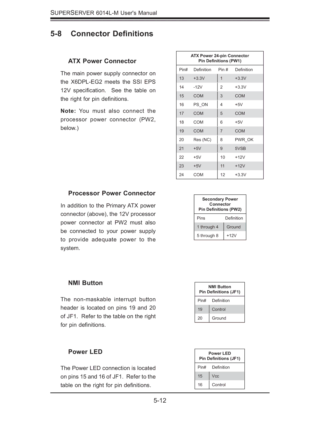
ATX Power Connector
The main power supply connector on the
Note: You must also connect the processor power connector (PW2, below.)
Processor Power Connector
In addition to the Primary ATX power connector (above), the 12V processor power connector at PW2 must also be connected to your power supply to provide adequate power to the system.
ATX Power
Pin Definitions (PW1)
Pin# | Defi nition | Pin # | Defi nition | |
13 | +3.3V | 1 | +3.3V | |
14 |
| +3.3V | ||
2 | ||||
15 | COM |
| COM | |
3 | ||||
16 | PS_ON |
| +5V | |
4 | ||||
17 | COM |
| COM | |
5 | ||||
18 | COM |
| +5V | |
6 | ||||
19 | COM |
| COM | |
7 | ||||
20 | Res (NC) |
| PWR_OK | |
8 | ||||
21 | +5V |
| 5VSB | |
9 | ||||
22 | +5V | 10 | +12V | |
23 | +5V | 11 | +12V | |
24 | COM | 12 | +3.3V | |
|
|
|
|
Secondary Power
Connector
Pin Definitions (PW2)
Pins | Defi nition | |
1 through 4 | Ground | |
5 through 8 | +12V | |
|
|
NMI Button
The
Power LED
The Power LED connection is located on pins 15 and 16 of JF1. Refer to the table on the right for pin defi nitions.
NMI Button
Pin Definitions (JF1)
Pin# Defi nition
19Control
20Ground
Power LED
Pin Definitions (JF1)
Pin# Defi nition
15Vcc
16Control