Chapter 5: Advanced Serverboard Setup
5-3 Processor and Heatsink Installation
! |
Avoid placing direct pressure to the top of the processor package. Also, never place the serverboard on a conductive surface. Always remove the power cord first before adding, removing or changing any hardware components.
The
Important: Make sure that you have installed the heatsink bracket(s) to the back of the serverboard fi rst.
Tools needed: a fl at head screwdriver, a Phillips screwdriver and thermal grease.
Installing the Processors
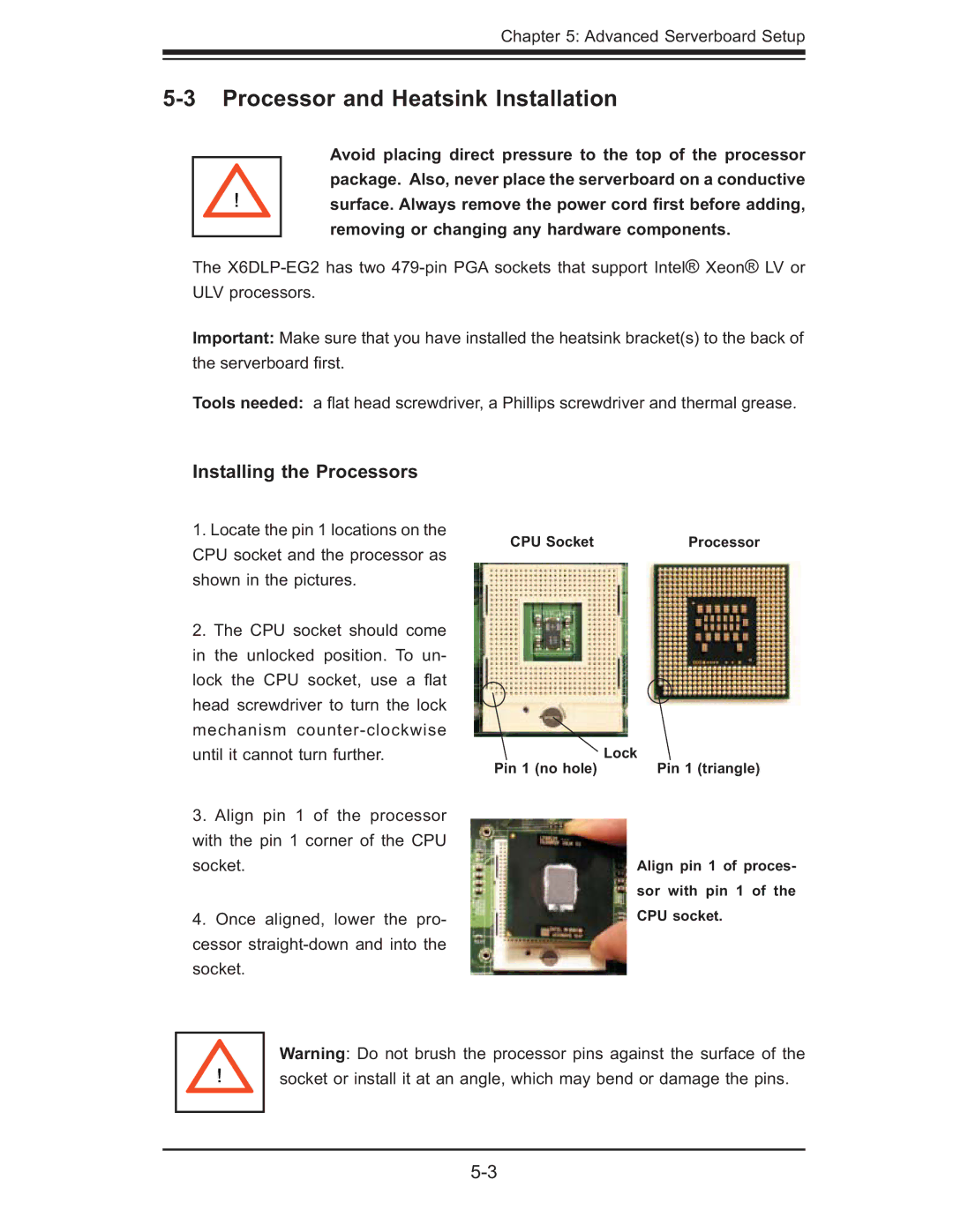
1.Locate the pin 1 locations on the CPU socket and the processor as shown in the pictures.
2.The CPU socket should come in the unlocked position. To un- lock the CPU socket, use a fl at head screwdriver to turn the lock mechanism
3.Align pin 1 of the processor with the pin 1 corner of the CPU socket.
4.Once aligned, lower the pro- cessor
CPU Socket | Processor |
Pin 1 (no hole) | Lock |
Pin 1 (triangle) |
Align pin 1 of proces- sor with pin 1 of the CPU socket.
! |
Warning: Do not brush the processor pins against the surface of the socket or install it at an angle, which may bend or damage the pins.