SUPERSERVER
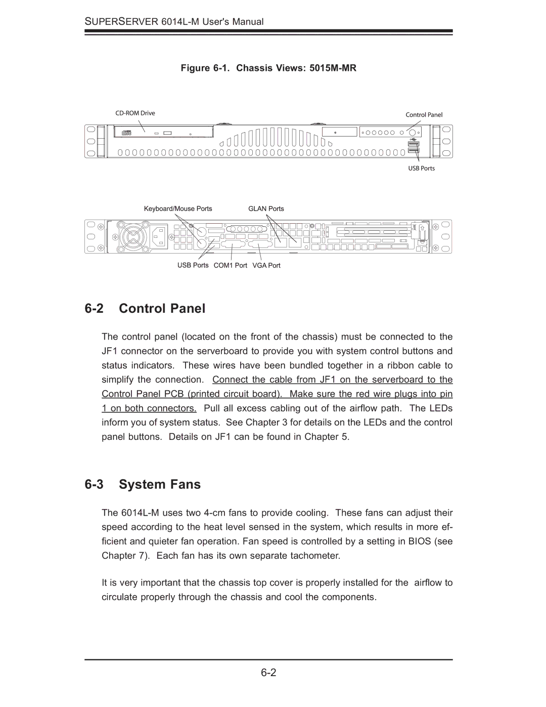
Figure 6-1. Chassis Views: 5015M-MR
6-2 Control Panel
The control panel (located on the front of the chassis) must be connected to the JF1 connector on the serverboard to provide you with system control buttons and status indicators. These wires have been bundled together in a ribbon cable to simplify the connection. Connect the cable from JF1 on the serverboard to the Control Panel PCB (printed circuit board). Make sure the red wire plugs into pin 1 on both connectors. Pull all excess cabling out of the airfl ow path. The LEDs inform you of system status. See Chapter 3 for details on the LEDs and the control panel buttons. Details on JF1 can be found in Chapter 5.
6-3 System Fans
The
ficient and quieter fan operation. Fan speed is controlled by a setting in BIOS (see Chapter 7). Each fan has its own separate tachometer.
It is very important that the chassis top cover is properly installed for the airfl ow to circulate properly through the chassis and cool the components.