SUPERSERVER
5-11 Parallel Port, Floppy, IDE and SATA Drive Connections
Note the following when connecting the fl oppy and hard disk drive cables:
•The fl oppy disk drive cable has seven twisted wires.
•A red mark on a wire typically designates the location of pin 1.
•A single fl oppy disk drive ribbon cable has 34 wires and two connectors to provide for two fl oppy disk drives. The connector with twisted wires always connects to drive A, and the connector that does not have twisted wires always connects to drive B.
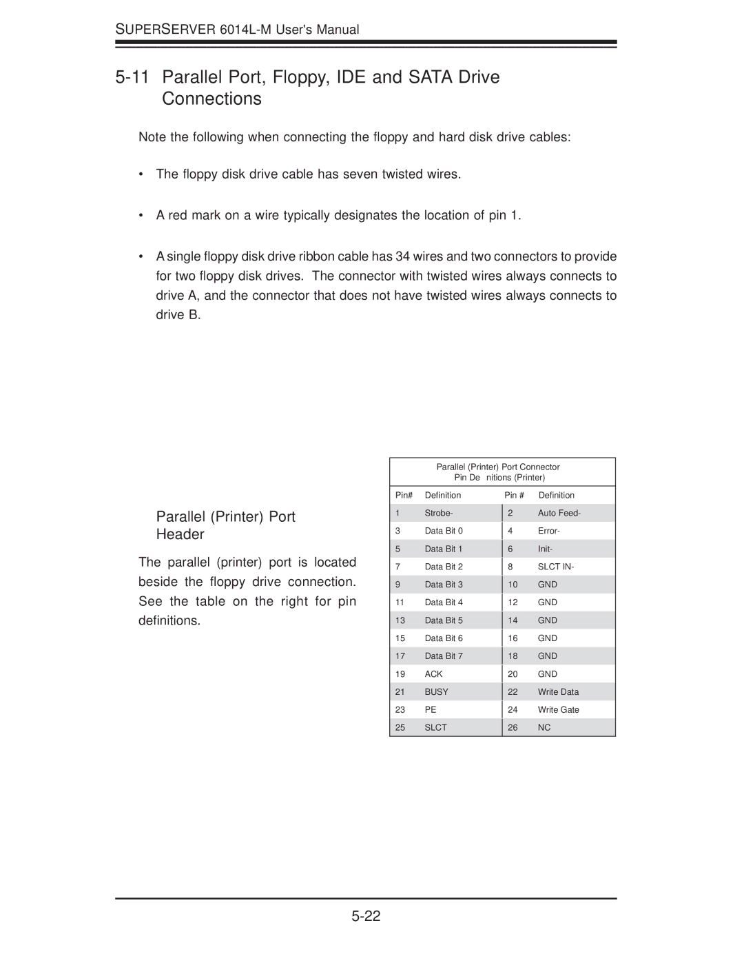
Parallel (Printer) Port
Header
The parallel (printer) port is located beside the fl oppy drive connection. See the table on the right for pin defi nitions.
Parallel (Printer) Port Connector
Pin Definitions (Printer)
Pin# | Definition | Pin # | Definition | |
1 | Strobe- | 2 | Auto Feed- | |
3 | Data Bit 0 |
| Error- | |
4 | ||||
5 | Data Bit 1 |
| Init- | |
6 | ||||
7 | Data Bit 2 |
| SLCT IN- | |
8 | ||||
9 | Data Bit 3 |
| GND | |
10 | ||||
11 | Data Bit 4 |
| GND | |
12 | ||||
13 | Data Bit 5 |
| GND | |
14 | ||||
15 | Data Bit 6 |
| GND | |
16 | ||||
17 | Data Bit 7 |
| GND | |
18 | ||||
19 | ACK |
| GND | |
20 | ||||
21 | BUSY |
| Write Data | |
22 | ||||
23 | PE |
| Write Gate | |
24 | ||||
25 | SLCT | 26 | NC | |
|
|
|
|