Chapter 5: Advanced Serverboard Setup
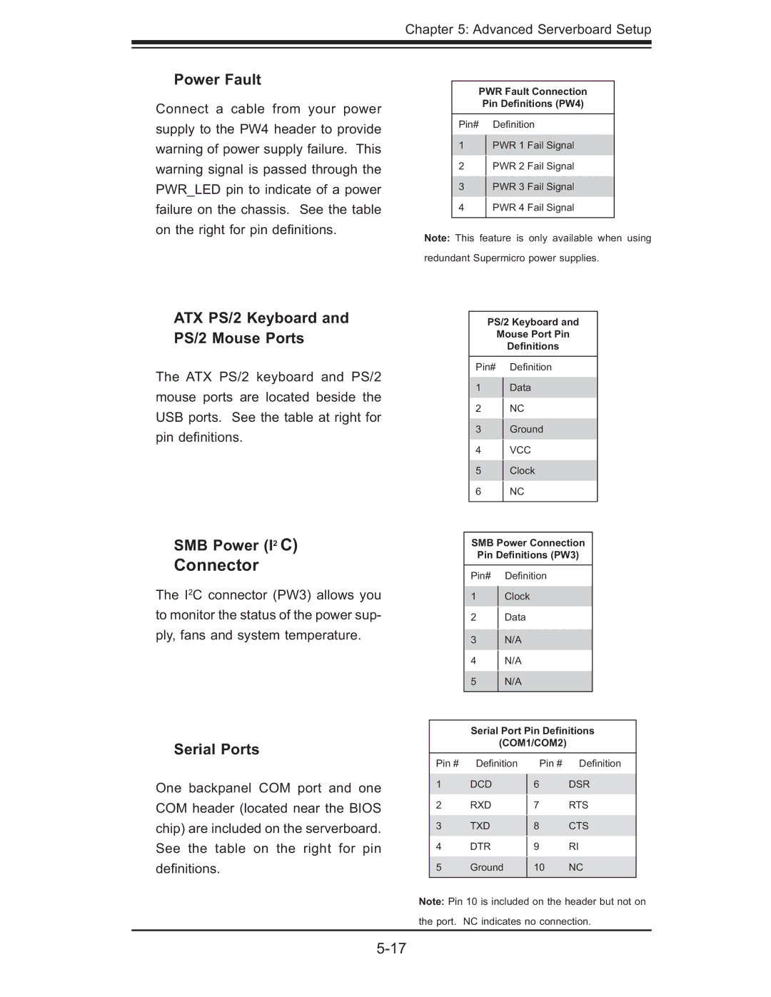
Power Fault
Connect a cable from your power supply to the PW4 header to provide warning of power supply failure. This warning signal is passed through the PWR_LED pin to indicate of a power failure on the chassis. See the table on the right for pin defi nitions.
ATX PS/2 Keyboard and PS/2 Mouse Ports
The ATX PS/2 keyboard and PS/2 mouse ports are located beside the USB ports. See the table at right for pin defi nitions.
PWR Fault Connection
Pin Definitions (PW4)
Pin# Defi nition
1PWR 1 Fail Signal
2 PWR 2 Fail Signal
3PWR 3 Fail Signal
4 PWR 4 Fail Signal
Note: This feature is only available when using redundant Supermicro power supplies.
PS/2 Keyboard and
Mouse Port Pin
Definitions
Pin# Defi nition
1Data
2NC
3Ground
4VCC
5Clock
6 NC
SMB Power (I2 C)
Connector
The I2C connector (PW3) allows you to monitor the status of the power sup- ply, fans and system temperature.
SMB Power Connection
Pin Definitions (PW3)
Pin# Defi nition
1Clock
2Data
3N/A
4N/A
5 N/A
Serial Ports
Serial Port Pin Definitions
(COM1/COM2)
One backpanel COM port and one COM header (located near the BIOS chip) are included on the serverboard. See the table on the right for pin defi nitions.
Pin # Defi nition
1DCD
2RXD
3TXD
4DTR
5Ground
Pin # Defi nition
6DSR
7RTS
8CTS
9RI
10 NC
Note: Pin 10 is included on the header but not on the port. NC indicates no connection.