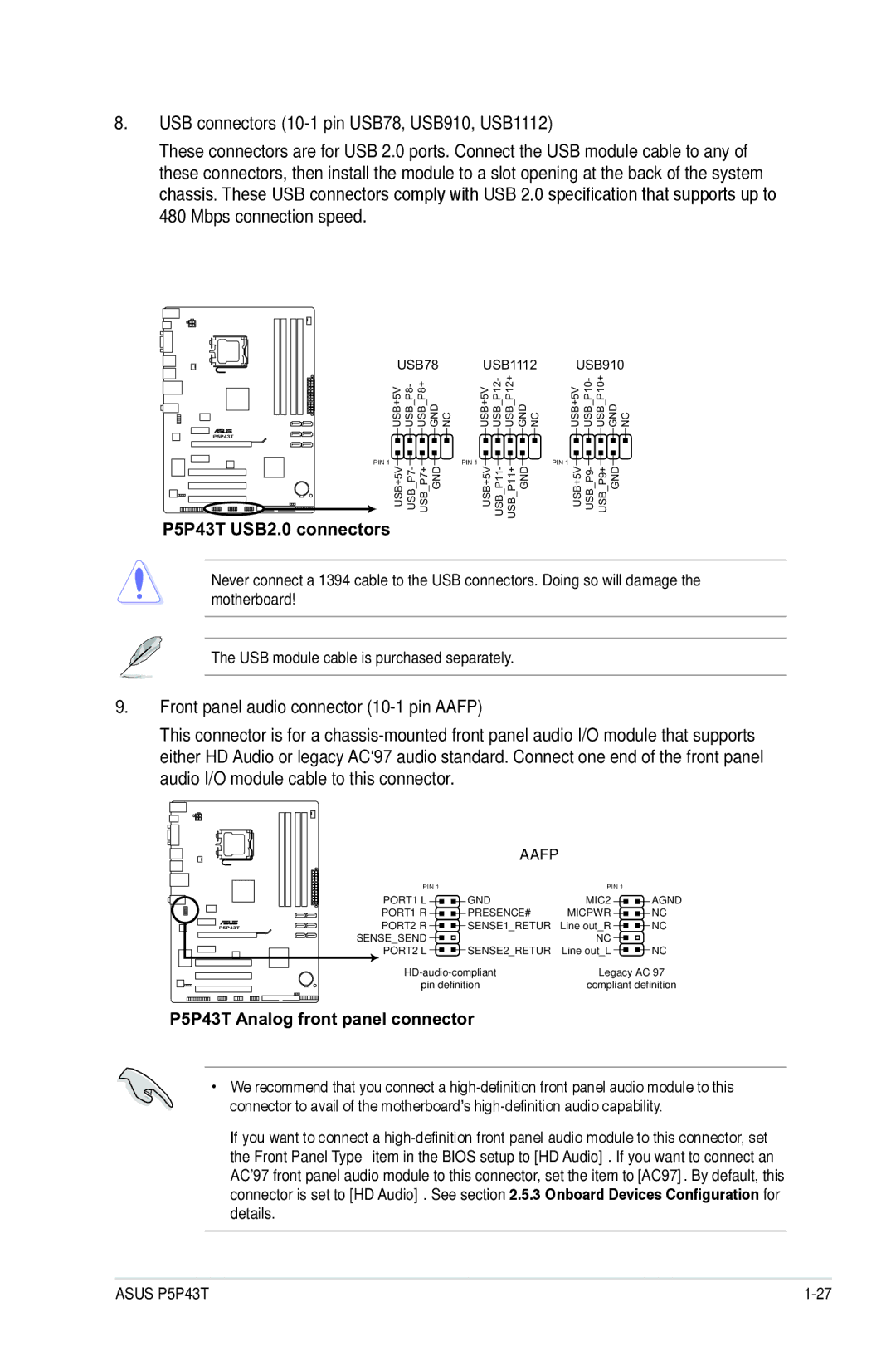
8.USB connectors (10-1 pin USB78, USB910, USB1112)
These connectors are for USB 2.0 ports. Connect the USB module cable to any of these connectors, then install the module to a slot opening at the back of the system chassis. These USB connectors comply with USB 2.0 specification that supports up to
480 Mbps connection speed.
USB78 | USB1112 | USB910 |
USB+5V USB_P8- USB_P8+ GND NC | USB+5V USB_P12- USB_P12+ GND NC | USB+5V USB_P10- USB_P10+ GND NC |
P5P43T
PIN 1
PIN 1
PIN 1
USB+5V USB P7- USB P7+ GND | USB+5V USB P11- USB P11+ GND | USB+5V USB P9- USB P9+ GND |
P5P43T USB2.0 connectors
Never connect a 1394 cable to the USB connectors. Doing so will damage the motherboard!
The USB module cable is purchased separately.
9.Front panel audio connector (10-1 pin AAFP)
This connector is for a
|
| AAFP |
|
|
| PIN 1 |
| PIN 1 |
|
| PORT1 L | GND | MIC2 | AGND |
| PORT1 R | PRESENCE# | MICPWR | NC |
P5P43T | PORT2 R | SENSE1_RETUR | Line out_R | NC |
| SENSE_SEND |
| NC |
|
| PORT2 L | SENSE2_RETUR | Line out_L | NC |
| Legacy AC’97 | |||
| pin definition | compliant definition | ||
P5P43T Analog front panel connector
•We recommend that you connect a
•If you want to connect a
ASUS P5P43T |