Intel Desktop Board D865PCD Technical Product Specification
2.11 Electrical Considerations
2.11.1DC Loading
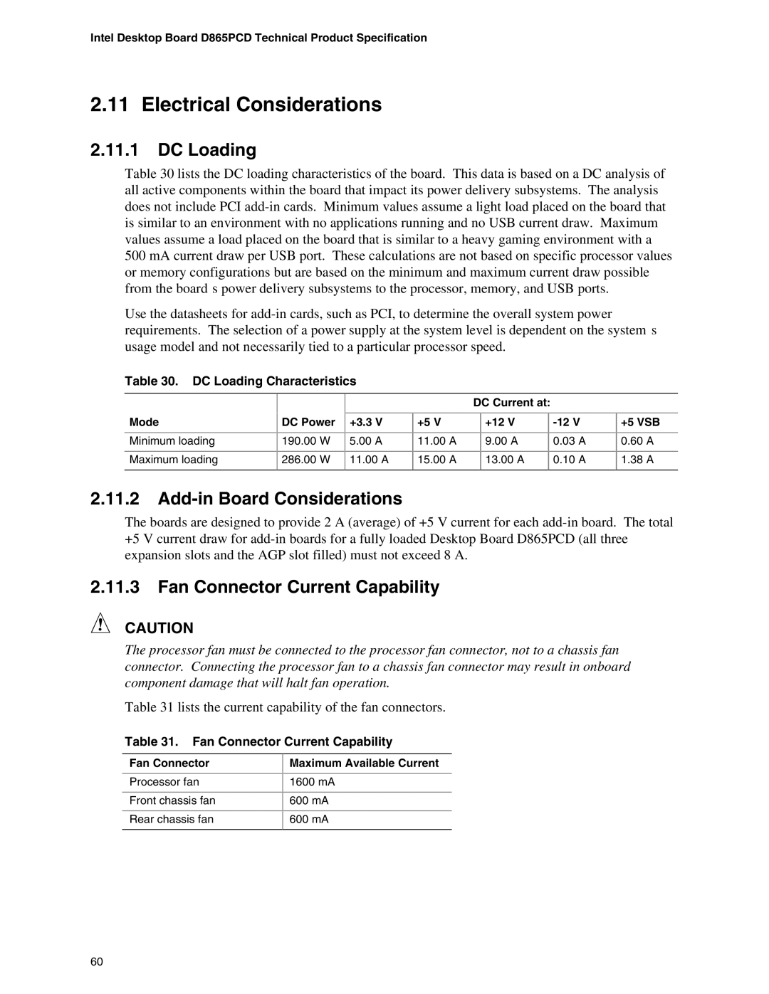
Table 30 lists the DC loading characteristics of the board. This data is based on a DC analysis of all active components within the board that impact its power delivery subsystems. The analysis does not include PCI
Use the datasheets for
Table 30. DC Loading Characteristics
Mode
Minimum loading
Maximum loading
DC Power
190.00W
286.00W
+3.3 V
5.00A
11.00A
| DC Current at: |
|
| ||
+5 V |
| +12 V |
|
| |
11.00 A |
| 9.00 A |
| 0.03 A |
|
15.00 A |
| 13.00 A |
| 0.10 A |
|
|
|
|
|
|
|
+5 VSB
0.60A
1.38A
2.11.2Add-in Board Considerations
The boards are designed to provide 2 A (average) of +5 V current for each
2.11.3Fan Connector Current Capability
CAUTION
The processor fan must be connected to the processor fan connector, not to a chassis fan connector. Connecting the processor fan to a chassis fan connector may result in onboard component damage that will halt fan operation.
Table 31 lists the current capability of the fan connectors.
Table 31. Fan Connector Current Capability
Fan Connector
Processor fan
Front chassis fan
Rear chassis fan
Maximum Available Current
1600 mA
600mA
600mA
60
