Intel Desktop Board D865PCD Technical Product Specification
1.1.3Block Diagram
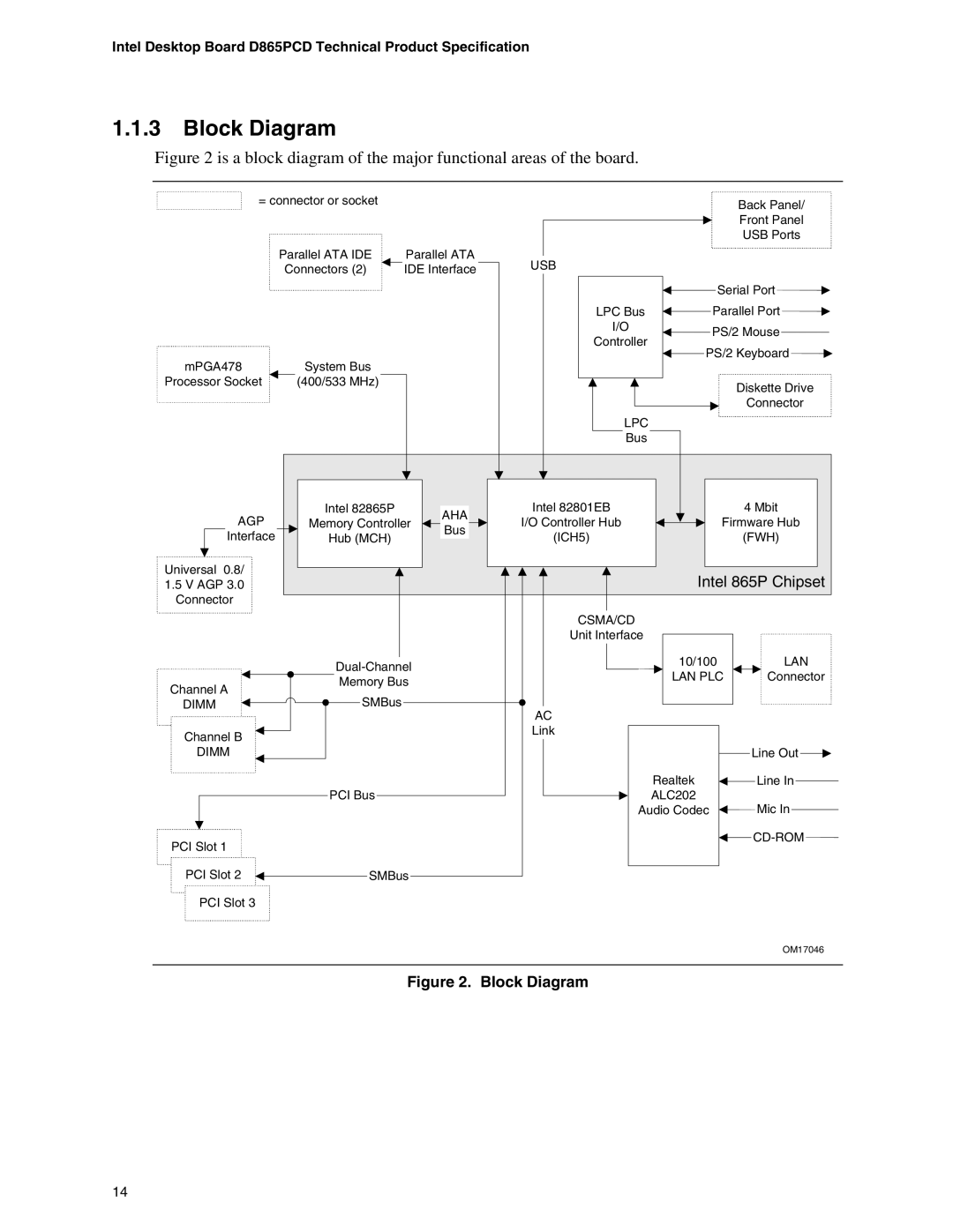
Figure 2 is a block diagram of the major functional areas of the board.
= connector or socket |
|
|
|
|
|
|
|
|
|
|
|
|
|
| Back Panel/ |
| |||||
|
|
|
|
|
|
|
|
|
|
|
|
|
|
|
| ||||||
|
|
|
|
|
|
|
|
|
|
|
|
|
|
| Front Panel |
| |||||
|
|
|
|
|
|
|
|
|
|
|
|
|
|
|
| ||||||
|
|
|
|
|
|
|
|
|
|
|
|
|
|
| USB Ports |
| |||||
|
|
|
|
|
|
|
|
|
|
|
|
|
|
|
|
|
|
|
|
|
|
Parallel ATA IDE |
| Parallel ATA |
|
|
|
|
|
|
|
|
|
|
|
|
|
|
|
|
|
|
|
|
|
| USB |
|
|
|
|
|
|
|
|
|
|
|
|
|
|
| |||
Connectors (2) |
| IDE Interface |
|
|
|
|
|
|
|
|
|
|
|
|
|
|
|
| |||
|
|
|
|
|
|
|
|
|
|
|
|
|
|
|
|
|
|
|
| ||
|
|
|
|
|
|
|
|
|
|
|
|
|
|
|
|
|
|
|
|
|
|
|
|
|
|
|
|
|
|
|
|
|
|
|
|
|
|
|
|
| |||
|
|
|
|
|
|
|
|
|
|
|
|
|
|
| Serial Port |
|
|
|
|
|
|
|
|
|
|
|
|
|
|
|
|
|
|
|
|
|
|
| |||||
|
|
|
|
|
|
|
|
|
|
|
|
|
|
|
|
|
|
|
| ||
|
|
|
|
|
|
|
|
|
|
|
|
|
|
|
|
|
|
|
|
|
|
|
|
|
|
|
|
|
| LPC Bus |
|
|
|
|
| Parallel Port |
|
|
|
| |||
|
|
|
|
|
|
|
|
|
|
|
|
|
|
| |||||||
|
|
|
|
|
|
|
| I/O |
|
|
|
|
|
|
|
|
|
|
|
|
|
|
|
|
|
|
|
|
|
|
|
|
|
| PS/2 Mouse |
|
|
|
|
| |||
|
|
|
|
|
|
|
| Controller |
|
|
|
|
|
|
|
|
| ||||
|
|
|
|
|
|
|
|
|
|
|
|
|
|
|
|
|
|
|
|
| |
|
|
|
|
|
|
|
|
|
|
|
|
|
|
|
|
|
|
|
|
| |
|
|
|
|
|
|
|
|
|
|
| PS/2 Keyboard |
|
|
| |||||||
|
|
|
|
|
|
|
|
|
|
|
|
|
|
| |||||||
|
|
|
|
|
|
|
|
|
|
|
|
|
| ||||||||
|
|
|
|
|
|
|
|
|
|
|
|
|
|
|
|
|
|
|
|
|
|
mPGA478 | System Bus |
|
|
|
| |
Processor Socket | (400/533 MHz) |
|
|
| Diskette Drive | |
|
|
|
|
| ||
|
|
|
|
| Connector | |
|
|
| LPC |
|
| |
|
|
| Bus |
|
| |
AGP | Intel 82865P | AHA | Intel 82801EB |
| 4 Mbit | |
Memory Controller | I/O Controller Hub | Firmware Hub | ||||
Bus | ||||||
Interface | Hub (MCH) | (ICH5) |
| (FWH) | ||
|
| |||||
Universal 0.8/ |
|
|
| Intel 865P Chipset | ||
1.5 V AGP 3.0 |
|
|
| |||
Connector |
|
|
|
|
| |
|
|
| CSMA/CD |
|
| |
|
|
| Unit Interface |
|
| |
|
|
| 10/100 | LAN | ||
|
|
| LAN PLC | Connector | ||
Channel A | Memory Bus |
|
| |||
|
|
|
| |||
SMBus |
|
|
|
| ||
DIMM |
| AC |
|
| ||
|
|
|
|
| ||
Channel B |
|
| Link |
|
| |
|
|
|
|
| ||
DIMM |
|
|
|
| Line Out | |
|
|
|
| Realtek | Line In | |
| PCI Bus |
|
| ALC202 | Mic In | |
|
|
| Audio Codec | |||
PCI Slot 1 |
|
|
|
| ||
|
|
|
|
| ||
PCI Slot 2 | SMBus |
|
|
|
| |
PCI Slot 3 |
|
|
|
|
| |
|
|
|
|
| OM17046 | |
Figure 2. Block Diagram
14