Intel Desktop Board D865PCD Technical Product Specification
1.9.2RJ-45 LAN Connector with Integrated LEDs
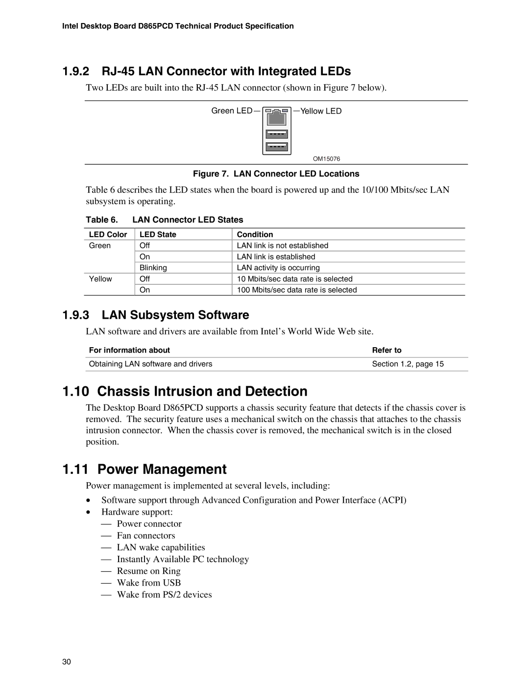
Two LEDs are built into the
Green LED ![]()
![]()
![]()
![]()
![]() Yellow LED
Yellow LED
OM15076
Figure 7. LAN Connector LED Locations
Table 6 describes the LED states when the board is powered up and the 10/100 Mbits/sec LAN subsystem is operating.
Table 6. LAN Connector LED States
LED Color
Green
Yellow
LED State
Off
On
Blinking
Off
On
Condition
LAN link is not established
LAN link is established
LAN activity is occurring
10 Mbits/sec data rate is selected
100 Mbits/sec data rate is selected
1.9.3LAN Subsystem Software
LAN software and drivers are available from Intel’s World Wide Web site.
For information about | Refer to |
Obtaining LAN software and drivers | Section 1.2, page 15 |
|
|
1.10 Chassis Intrusion and Detection
The Desktop Board D865PCD supports a chassis security feature that detects if the chassis cover is removed. The security feature uses a mechanical switch on the chassis that attaches to the chassis intrusion connector. When the chassis cover is removed, the mechanical switch is in the closed position.
1.11 Power Management
Power management is implemented at several levels, including:
•Software support through Advanced Configuration and Power Interface (ACPI)
•Hardware support:
Power connector
Fan connectors
LAN wake capabilities
Instantly Available PC technology
Resume on Ring
Wake from USB
Wake from PS/2 devices
30