Technical Reference
✏NOTE
Some additional I/O addresses are not available due to ICH5 address aliasing. The ICH5 data sheet provides more information on address aliasing.
For information about | Refer to |
Obtaining the ICH5 data sheet | Section 1.2 on page 15 |
|
|
2.5 PCI Configuration Space Map
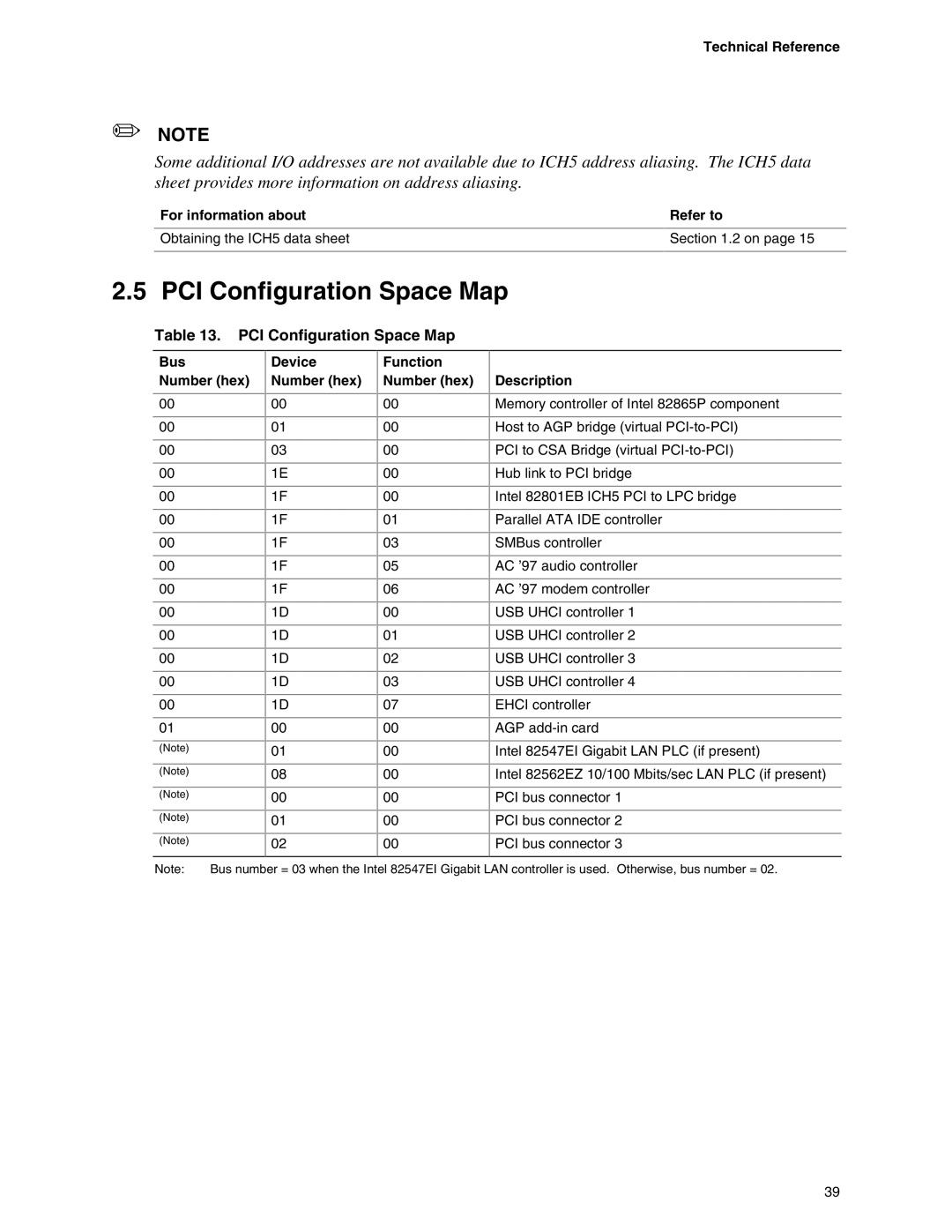
Table 13. PCI Configuration Space Map
Bus
Number (hex)
Device Number (hex)
Function Number (hex)
Description
00 |
| 00 | 00 | Memory controller of Intel 82865P component |
00 |
| 01 | 00 | Host to AGP bridge (virtual |
00 |
| 03 | 00 | PCI to CSA Bridge (virtual |
00 |
| 1E | 00 | Hub link to PCI bridge |
00 |
| 1F | 00 | Intel 82801EB ICH5 PCI to LPC bridge |
00 |
| 1F | 01 | Parallel ATA IDE controller |
00 |
| 1F | 03 | SMBus controller |
00 |
| 1F | 05 | AC ’97 audio controller |
00 |
| 1F | 06 | AC ’97 modem controller |
00 |
| 1D | 00 | USB UHCI controller 1 |
00 |
| 1D | 01 | USB UHCI controller 2 |
00 |
| 1D | 02 | USB UHCI controller 3 |
00 |
| 1D | 03 | USB UHCI controller 4 |
00 |
| 1D | 07 | EHCI controller |
01 |
| 00 | 00 | AGP |
(Note) |
| 01 | 00 | Intel 82547EI Gigabit LAN PLC (if present) |
(Note) |
| 08 | 00 | Intel 82562EZ 10/100 Mbits/sec LAN PLC (if present) |
(Note) |
| 00 | 00 | PCI bus connector 1 |
(Note) |
| 01 | 00 | PCI bus connector 2 |
(Note) |
| 02 | 00 | PCI bus connector 3 |
Note: | Bus number = 03 when the Intel 82547EI Gigabit LAN controller is used. Otherwise, bus number = 02. | |||
39
