Intel Desktop Board D865PCD Technical Product Specification
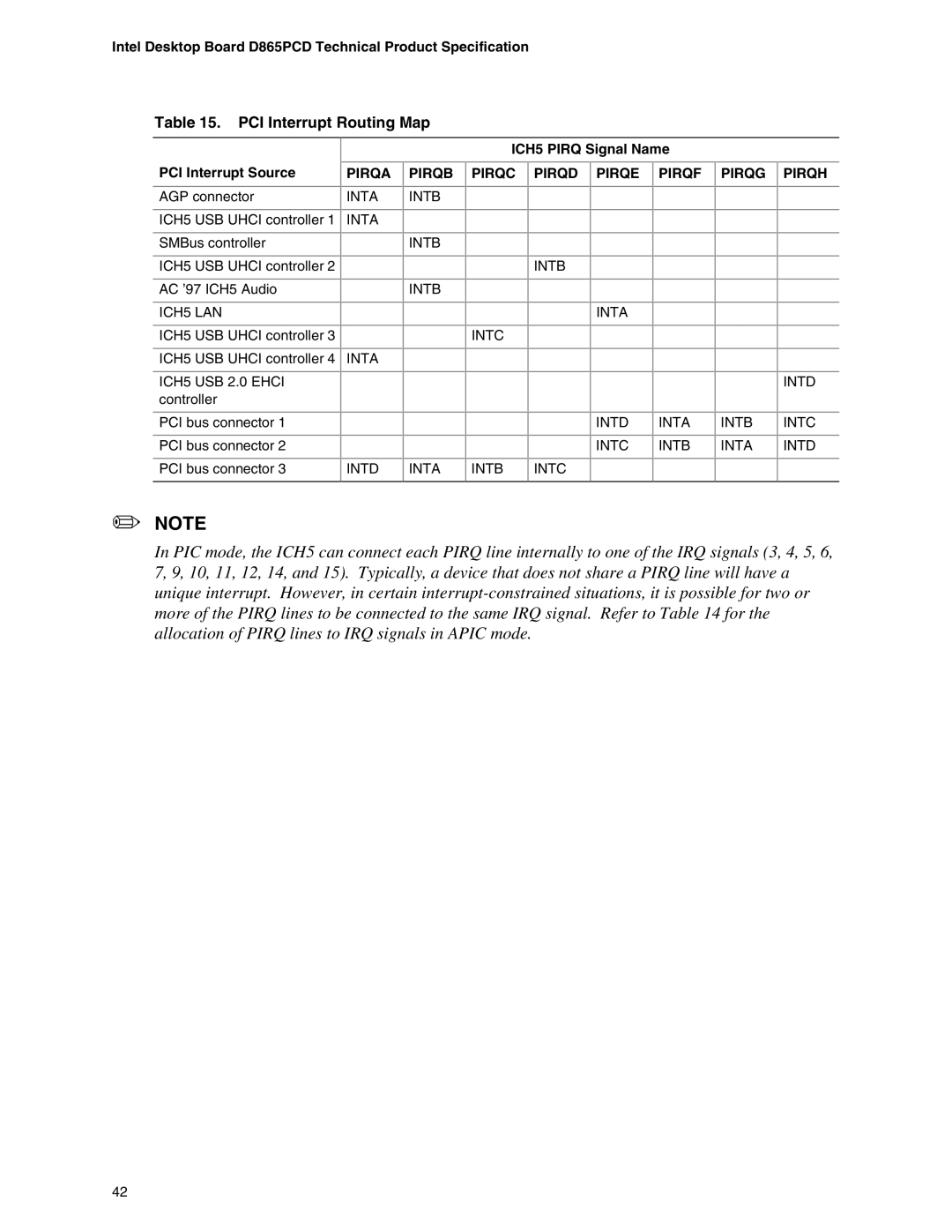
Table 15. PCI Interrupt Routing Map
ICH5 PIRQ Signal Name
PCI Interrupt Source | PIRQA |
AGP connector | INTA |
ICH5 USB UHCI controller 1 | INTA |
SMBus controller |
|
ICH5 USB UHCI controller 2 |
|
AC ’97 ICH5 Audio |
|
ICH5 LAN |
|
ICH5 USB UHCI controller 3 |
|
ICH5 USB UHCI controller 4 | INTA |
ICH5 USB 2.0 EHCI |
|
controller |
|
PCI bus connector 1 |
|
PCI bus connector 2 |
|
PCI bus connector 3 | INTD |
PIRQB
INTB
INTB
INTB
INTA
PIRQC PIRQD PIRQE
INTB
INTA
INTC
INTD
INTC
INTB | INTC |
PIRQF
INTA
INTB
PIRQG PIRQH
INTD
INTB INTC
INTA INTD
✏NOTE
In PIC mode, the ICH5 can connect each PIRQ line internally to one of the IRQ signals (3, 4, 5, 6, 7, 9, 10, 11, 12, 14, and 15). Typically, a device that does not share a PIRQ line will have a unique interrupt. However, in certain
42