Strainer — Periodic
Motormaster® V Controller — The optional or ac- cessory Motormaster V controller uses a 0 to 5 vdc signal input from a pressure transducer attached to the liquid line ser- vice valve gage port on each circuit. See Fig. 37. The pressure transducer is connected to terminals 2, 5 and 6 on the control- ler. The controller is factory configured and requires no field programming. If a situation arises where the drive does not function properly, the information provided below and Table 37 can be used to troubleshoot the drive.
If input power has not been applied to the drive for a period of time exceeding three years (due to storage, etc.), the electrolytic DC bus capacitors within the drive can change internally, resulting in excessive leakage current. This can result in premature failure of the capacitors if the drive is operated after such a long period of inactivity or storage. In order to reform the capacitors and prepare the drive for operation after a long period of inactivity, apply input power to the drive for 8 hours prior to actually operating the motor. Before attempting to operate the drive, motor, and driven equipment, be sure all procedures pertaining to installation and wiring have been properly followed.
DO NOT connect incoming AC power to output terminals T1, T2, and T3! Severe damage to the drive will result. Do not continuously cycle input power to the drive more than once every two minutes. Damage to the drive will result.
Hazard of electrical shock! Wait three minutes after discon- necting incoming power before servicing drive. Capacitors retain charge after power is removed. Drive assembly includes externally mounted current limiting resistors. Use extreme caution when servicing the drive.
When configured as shown below, this equipment is designed to start when it receives line power. Ensure that all personnel are clear of fans and guards are installed before applying power.
GENERAL OPERATION — This control varies condenser fan speed based on liquid pressure. The control is a Variable Frequency Drive (VFD) and is only compatible with motors rated for use with VFDs. The accompanying pressure transduc- er has a 0 to 5 v output range corresponding to a
This system is a reverse acting,
NOTE: Dimensions in ( ) are in millimeters.
Fig. 35 — Fluid-Side Temperature Sensors
(T1 and T2)
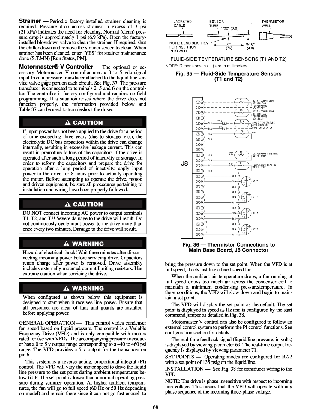
Fig. 36 — Thermistor Connections to
Main Base Board, J8 Connector
bring the pressure down to the set point. When the VFD is at full speed, it acts just like a fixed speed fan.
When the ambient air temperature drops, a fan running at full speed draws too much air across the condenser coil to maintain a minimum condensing pressure/temperature. In these conditions, the VFD will slow down and begin to main- tain a set point.
The VFD will display the set point as the default. The set point is displayed in speed as Hz and is configured by the start command jumper as detailed in Fig. 38.
Motormaster V control can also be configured to follow an external control system to perform the PI control functions. See configuration section for details.
The
SET POINTS — Operating modes are configured for
INSTALLATION — See Fig. 38 for transducer wiring to the VFD.
NOTE: The drive is phase insensitive with respect to incoming line voltage. This means that the VFD will operate with any phase sequence of the incoming
68