•Thoroughly rinse all surfaces with low velocity clean water using downward rinsing motion of water spray nozzle. Protect fins from damage from the spray nozzle.
Harsh Chemical and Acid Cleaners — Harsh chemical, household bleach or acid cleaners should not be used to clean outdoor or indoors coils of any kind. These cleaners can be very difficult to rinse out of the coil and can acceler- ate corrosion at the fin/tube interface where dissimilar materials are in contact. If there is dirt below the surface of the coil, use the Environmentally Sound Coil Cleaner as described above.
High Velocity Water or Compressed Air — High veloc- ity water from a pressure washer, garden hose or com- pressed air should never be used to clean a coil. The force of the water or air jet will bend the fin edges and increase airside pressure drop. Reduced unit performance or nui- sance unit shutdown may occur.
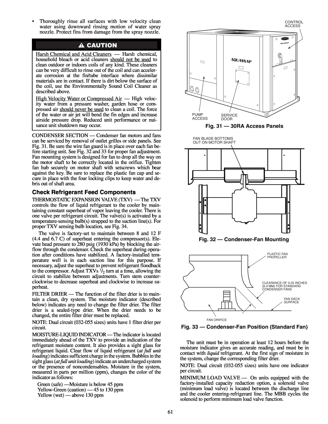
CONDENSER SECTION — Condenser fan motors and fans can be serviced by removal of outlet grilles or side panels. See Fig. 31. Be sure the wire fan guard is in place over each fan be- fore starting unit. See Fig. 32 and 33 for proper fan adjustment. Fan mounting system is designed for fan to drop all the way on the motor shaft to be correctly located in the orifice. Tighten fan hub securely on motor shaft with setscrews which bear against the key. Be sure to replace the plastic fan cap and se- cure in place with the four locking clips to keep water and de- bris out of shaft area.
Check Refrigerant Feed Components
THERMOSTATIC EXPANSION VALVE (TXV) — The TXV controls the flow of liquid refrigerant to the cooler by main- taining constant superheat of vapor leaving the cooler. There is one valve per refrigerant circuit. The valve(s) is activated by a
The valve is
FILTER DRIER — The function of the filter drier is to main- tain a clean, dry system. The moisture indicator (described below) indicates any need to change the filter drier. The filter drier is a
NOTE: Dual circuit
Green (safe)
CONTROL
ACCESS
PUMPSERVICE
ACCESS DOOR
Fig. 31 — 30RA Access Panels
FAN BLADE BOTTOMS
OUT ON MOTOR SHAFT
Fig. 32 — Condenser-Fan Mounting
PLASTIC FAN
PROPELLER
CLEARANCE OF 0.25 INCHES (6.4 MM) FOR STANDARD CONDENSER FANS
FAN DECK
SURFACE
FAN ORIFICE
Fig. 33 — Condenser-Fan Position (Standard Fan)
The unit must be in operation at least 12 hours before the moisture indicator gives an accurate reading, and must be in contact with liquid refrigerant. At the first sign of moisture in the system, change the corresponding filter drier.
NOTE: Dual circuit
MINIMUM LOAD VALVE — On units equipped with the
61