As part of a pump maintenance routine, the pumps can be started to maintain lubrication to the pump seal. To utilize this function, Cooler Pmp Periodic Start (PM.P.S) [Configuration, UNIT] must be set to YES. This option is set to NO as the fac- tory default. If feature is enabled and the pump(s) are not operating, then the pumps will be operated every other day for 2 seconds starting at 14:00 hours. If a pump has failed and has an active Alert condition, it will not be started that day.
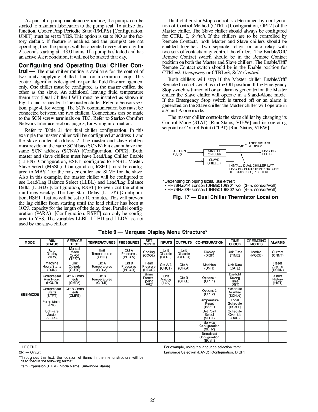
Configuring and Operating Dual Chiller Con- trol — The dual chiller routine is available for the control of two units supplying chilled fluid on a common loop. This control algorithm is designed for parallel fluid flow arrangement only. One chiller must be configured as the master chiller, the other as the slave. An additional leaving fluid temperature thermistor (Dual Chiller LWT) must be installed as shown in Fig. 17 and connected to the master chiller. Refer to Sensors sec- tion, page 4, for wiring. The SCN communication bus must be connected between the two chillers. Connections can be made to the SCN screw terminals on TB3. Refer to Sterlco Comfort Network Interface section, page 3, for wiring information.
Refer to Table 21 for dual chiller configuration. In this example the master chiller will be configured at address 1 and the slave chiller at address 2. The master and slave chillers must reside on the same SCN bus (SCNB) but cannot have the same SCN address (SCNA) [Configuration, OPT2]. Both master and slave chillers must have Lead/Lag Chiller Enable (LLEN) [Configuration, RSET] configured to ENBL. Master/ Slave Select (MSSL) [Configuration, RSET] must be config- ured to MAST for the master chiller and SLVE for the slave. Also in this example, the master chiller will be configured to use Lead/Lag Balance Select (LLBL) and Lead/Lag Balance Delta (LLBD) [Configuration, RSET] to even out the chiller
Dual chiller start/stop control is determined by configura- tion of Control Method (CTRL) [Configuration, OPT2] of the Master chiller. The Slave chiller should always be configured for CTRL=0, Switch. If the chillers are to be controlled by Remote Contacts, both Master and Slave chillers should be enabled together. Two separate relays or one relay with two sets of contacts may control the chillers. The Enable/Off/ Remote Contact switch should be in the Remote Contact position on both the Master and Slave chillers. The Enable/Off/ Remote Contact switch should be in the Enable position for CTRL=2, Occupancy or CTRL=3, SCN Control.
Both chillers will stop if the Master chiller Enable/Off/ Remote Contact switch is in the Off position. If the Emergency Stop switch is turned off or an alarm is generated on the Master chiller the Slave chiller will operate in a
The master chiller controls the slave chiller by changing its Control Mode (STAT) [Run Status, VIEW] and its operating setpoint or Control Point (CTPT) [Run Status, VIEW].
THERMISTOR
WIRING*
RETURN | MASTER |
| LEAVING | ||
FLUID |
|
| CHILLER |
| FLUID |
SLAVE
CHILLER
INSTALL DUAL CHILLER LWT
LEAVING FLUID TEMPERATURE
THERMISTOR (T10) HERE
*Depending on piping sizes, use either:
•HH79NZ014 sensor/10HB50106801 well
•HH79NZ029 sensor/10HB50106802 well
Fig. 17 — Dual Chiller Thermistor Location
Table 9 — Marquee Display Menu Structure*
MODE | RUN | SERVICE | TEMPERATURES | PRESSURES | SET | INPUTS | OUTPUTS | CONFIGURATION | TIME | OPERATING | ALARMS | |
STATUS | TEST | POINTS | CLOCK | MODES | ||||||||
|
|
|
|
|
|
| ||||||
| Auto | Manual | Unit | Ckt A |
| Unit | Unit |
|
|
|
| |
| Mode | Cooling | Display | Unit Time | Modes | Current | ||||||
| Display | Temperatures | Pressures | Discrete | Discrete | |||||||
| On/Off | (COOL) | (DISP) | (TIME) | (MODE) | (CRNT) | ||||||
| (VIEW) | (UNIT) | (PRC.A) | (GEN.I) | (GEN.O) | |||||||
| (TEST) |
|
|
|
|
| ||||||
|
|
|
|
|
|
|
|
|
|
| ||
| Machine | Unit | Ckt A | Ckt B | Head | Ckt A/B | Ckt A | Machine | Unit Date |
| Reset | |
| Hours/Starts | Outputs | Temperatures | Pressures | Pressure |
| Alarms | |||||
| (CRCT) | (CIR.A) | (UNIT) | (DATE) |
| |||||||
| (RUN) | (OUTS) | (CIR.A) | (PRC.B) | (HEAD) |
| (RCRN) | |||||
|
|
|
|
|
| |||||||
| Compressor | Ckt A Comp | Ckt B |
| Brine | Unit |
|
| Daylight |
| Alarm | |
|
| Freeze- | Ckt B | Options 1 | Saving |
| ||||||
| Run Hours | Tests | Temperatures |
| Analog |
| History | |||||
|
| point | (CIR.B) | (OPT1) | Time |
| ||||||
| (HOUR) | (CMPA) | (CIR.B) |
|
| (HIST) | ||||||
|
| (FRZ) |
|
| (DST) |
| ||||||
|
|
|
|
|
|
|
|
|
| |||
| Compressor | Ckt B Comp |
|
|
|
|
| Options 2 | Schedule |
|
| |
| Starts | Tests |
|
|
|
|
| Number |
|
| ||
|
|
|
|
| (OPT2) |
|
| |||||
(STRT) | (CMPB) |
|
|
|
|
| (SCH.N) |
|
| |||
|
|
|
|
|
|
|
|
| ||||
| Pump Maint. |
|
|
|
|
|
| Temperature | Local |
|
| |
|
|
|
|
|
|
| Reset | Schedule |
|
| ||
| (PM) |
|
|
|
|
|
|
|
| |||
|
|
|
|
|
|
| (RSET) | (SCH.L) |
|
| ||
|
|
|
|
|
|
|
|
|
| |||
| Software |
|
|
|
|
|
| Set Point | Schedule |
|
| |
| Version |
|
|
|
|
|
| Select | Override |
|
| |
| (VERS) |
|
|
|
|
|
| (SLCT) | (OVR) |
|
| |
|
|
|
|
|
|
|
| Service |
|
|
| |
|
|
|
|
|
|
|
| Configuration |
|
|
| |
|
|
|
|
|
|
|
| (SERV) |
|
|
| |
|
|
|
|
|
|
|
| Broadcast |
|
|
| |
|
|
|
|
|
|
|
| Configuration |
|
|
| |
|
|
|
|
|
|
|
| (BCST) |
|
|
| |
LEGEND |
|
|
|
|
| For example, using the language selection item: |
|
| ||||
Ckt — Circuit |
|
|
|
|
| Language Selection (LANG) [Configuration, DISP] |
|
| ||||
*Throughout this text, the location of items in the menu structure will be described in the following format:
Item Expansion (ITEM) [Mode Name,
26