2.0F (1.1 C) cooler ∆T and 0° F (0° C) reset at 10.0 F (5.6 C) cooler ∆T. The variable RT.NO should be set to the cooler temperature difference (∆T) where no chilled water tempera- ture reset should occur. The variable RT.F should be set to the cooler temperature difference where the maximum chilled wa- ter temperature reset should occur. The variable RM.DG should be set to the maximum amount of reset desired.
To verify that reset is functioning correctly proceed to Run Status mode,
Under normal operation, the chiller will maintain a constant leaving fluid temperature approximately equal to the chilled fluid set point. As the cooler load varies, the entering cooler fluid will change in proportion to the load as shown in Fig. 18. Usually the chiller size and
Return temperature reset allows for the leaving temperature set point to be reset upward as a function of the return fluid temperature or, in effect, the building load.
Figures 19 and 20 are examples of outdoor air and space temperature resets.
LEGEND
EWT — Entering Water (Fluid) Temperature
LWT — Leaving Water (Fluid) Temperature
Fig. 18 — Standard Chilled Fluid
Temperature Control — No Reset
Demand Limit — Demand Limit is a feature that allows the unit capacity to be limited during periods of peak energy us- age. There are 3 types of demand limiting that can be config- ured. The first type is through
NOTE: The
To use Demand Limit, select the type of demand limiting to use. Then configure the Demand Limit set points based on the type selected.
DEMAND LIMIT
LEGEND
LWT — Leaving Water (Fluid) Temperature
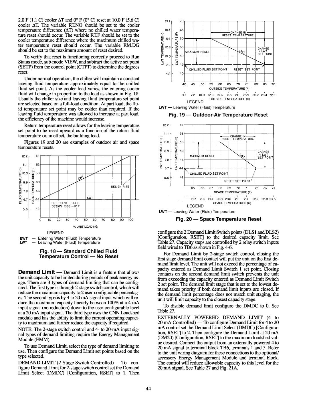
Fig. 19 — Outdoor-Air Temperature Reset
LEGEND
LWT — Leaving Water (Fluid) Temperature
Fig. 20 — Space Temperature Reset
configure the 2 Demand Limit Switch points (DLS1 and DLS2) [Configuration, RSET] to the desired capacity limit. See Table 27. Capacity steps are controlled by 2 relay switch inputs field wired to TB6 as shown in Fig.
For Demand Limit by
To disable demand limit configure the DMDC to 0. See Table 27.
EXTERNALLY POWERED DEMAND LIMIT (4 to 20 mA Controlled) — To configure Demand Limit for 4 to 20 mA control set the Demand Limit Select (DMDC) [Configura- tion, RSET] to 2. Then configure the Demand Limit at 20 mA (DM20) [Configuration, RSET] to the maximum loadshed val- ue desired. Connect the output from an externally powered 4 to 20 mA signal to terminal block TB6, terminals 1 and 5. Refer to the unit wiring diagram for these connections to the optional/ accessory Energy Management Module and terminal block. The control will reduce allowable capacity to this level for the 20 mA signal. See Table 27 and Fig. 21A.
44