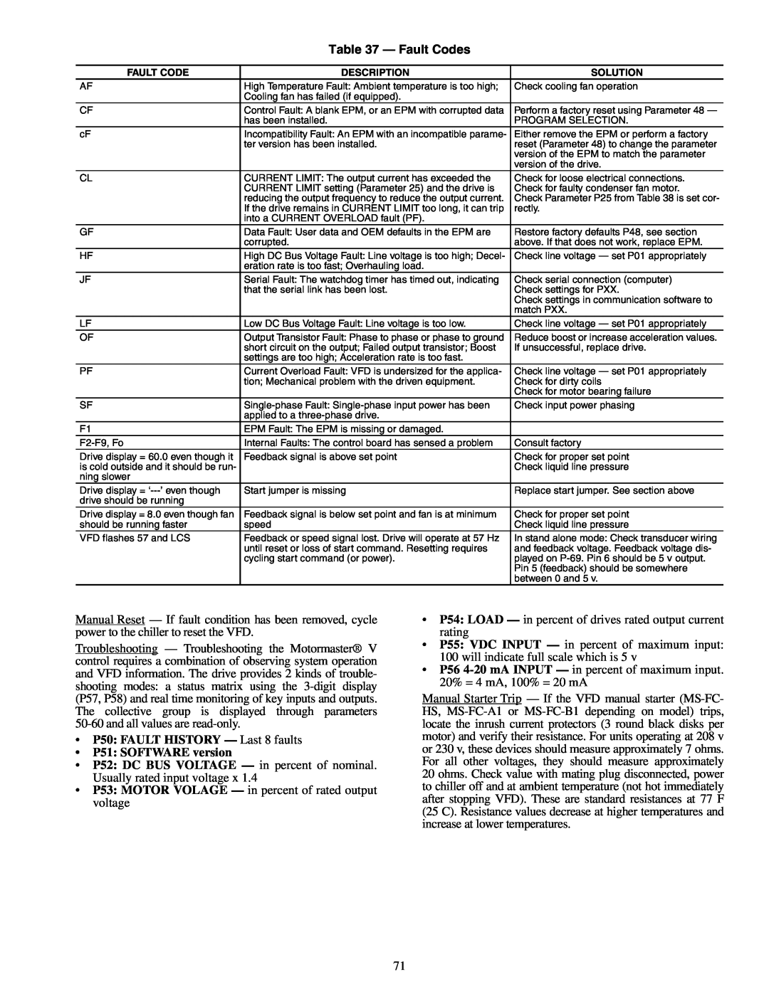
Table 37 — Fault Codes
FAULT CODE | DESCRIPTION | SOLUTION |
AF | High Temperature Fault: Ambient temperature is too high; | Check cooling fan operation |
| Cooling fan has failed (if equipped). |
|
CF | Control Fault: A blank EPM, or an EPM with corrupted data | Perform a factory reset using Parameter 48 — |
| has been installed. | PROGRAM SELECTION. |
cF | Incompatibility Fault: An EPM with an incompatible parame- | Either remove the EPM or perform a factory |
| ter version has been installed. | reset (Parameter 48) to change the parameter |
|
| version of the EPM to match the parameter |
|
| version of the drive. |
CL | CURRENT LIMIT: The output current has exceeded the | Check for loose electrical connections. |
| CURRENT LIMIT setting (Parameter 25) and the drive is | Check for faulty condenser fan motor. |
| reducing the output frequency to reduce the output current. | Check Parameter P25 from Table 38 is set cor- |
| If the drive remains in CURRENT LIMIT too long, it can trip | rectly. |
| into a CURRENT OVERLOAD fault (PF). |
|
GF | Data Fault: User data and OEM defaults in the EPM are | Restore factory defaults P48, see section |
| corrupted. | above. If that does not work, replace EPM. |
HF | High DC Bus Voltage Fault: Line voltage is too high; Decel- | Check line voltage — set P01 appropriately |
| eration rate is too fast; Overhauling load. |
|
JF | Serial Fault: The watchdog timer has timed out, indicating | Check serial connection (computer) |
| that the serial link has been lost. | Check settings for PXX. |
|
| Check settings in communication software to |
|
| match PXX. |
LF | Low DC Bus Voltage Fault: Line voltage is too low. | Check line voltage — set P01 appropriately |
OF | Output Transistor Fault: Phase to phase or phase to ground | Reduce boost or increase acceleration values. |
| short circuit on the output; Failed output transistor; Boost | If unsuccessful, replace drive. |
| settings are too high; Acceleration rate is too fast. |
|
PF | Current Overload Fault: VFD is undersized for the applica- | Check line voltage — set P01 appropriately |
| tion; Mechanical problem with the driven equipment. | Check for dirty coils |
|
| Check for motor bearing failure |
SF | Check input power phasing | |
| applied to a |
|
F1 | EPM Fault: The EPM is missing or damaged. |
|
Internal Faults: The control board has sensed a problem | Consult factory | |
Drive display = 60.0 even though it | Feedback signal is above set point | Check for proper set point |
is cold outside and it should be run- |
| Check liquid line pressure |
ning slower |
|
|
Drive display = | Start jumper is missing | Replace start jumper. See section above |
drive should be running |
|
|
Drive display = 8.0 even though fan | Feedback signal is below set point and fan is at minimum | Check for proper set point |
should be running faster | speed | Check liquid line pressure |
VFD flashes 57 and LCS | Feedback or speed signal lost. Drive will operate at 57 Hz | In stand alone mode: Check transducer wiring |
| until reset or loss of start command. Resetting requires | and feedback voltage. Feedback voltage dis- |
| cycling start command (or power). | played on |
|
| Pin 5 (feedback) should be somewhere |
|
| between 0 and 5 v. |
Manual Reset — If fault condition has been removed, cycle power to the chiller to reset the VFD.
Troubleshooting — Troubleshooting the Motormaster® V control requires a combination of observing system operation and VFD information. The drive provides 2 kinds of trouble- shooting modes: a status matrix using the
•P50: FAULT HISTORY — Last 8 faults
•P51: SOFTWARE version
•P52: DC BUS VOLTAGE — in percent of nominal. Usually rated input voltage x 1.4
•P53: MOTOR VOLAGE — in percent of rated output voltage
•P54: LOAD — in percent of drives rated output current rating
•P55: VDC INPUT — in percent of maximum input: 100 will indicate full scale which is 5 v
•P56
Manual Starter Trip — If the VFD manual starter
71