SERVICE
ELECTRIC SHOCK HAZARD.
Turn off all power to unit before servicing. The ENABLE/OFF/REMOTE CONTACT switch on control panel does not shut off control power; use field disconnect.
Electronic Components
CONTROL COMPONENTS — Unit uses an advanced elec- tronic control system that normally does not require service. For details on controls refer to Operating Data section.
Access to the compressors is through latched panels from beneath the control box on all models or from opposite the coil side (sizes
Compressor Replacement (Refer to Fig. 27-
30)— All models contain scroll compressors and have from one to four compressors. The size
Unscrew the junction box cover bolts and disconnect the compressor power and ground connections. Remove the cable from the compressor junction box. Remove the connections from the internal thermostat and
Be sure the oil equalization line fitting is removed from the old compressor and installed on the new compressor for those models with dual compressor circuits. The compressors are bolted to the unit basepan. Remove the 4 bolts holding the compressor to the basepan. Save the mounting hardware for use with the new compressor. Carefully cut the compressor suction and discharge lines with a tubing cutter as close to the compressor as feasible. For dual compressor circuits, do NOT disturb the suction line tee at the backside of the compressors. This tee contains a special tube that is required for proper oil return. Remove
Slide the new compressor in place on the basepan. Lifting one side of the compressor at a time, replace all of the compres- sor mounting grommets. Using new tubing or couplings as re- quired, reconnect compressor suction and discharge lines. Us- ing hardware saved, reinstall the mounting bolts and washers through the compressor feet. Using proper techniques, braze suction and discharge lines and check for leaks. Reconnect oil equalization line on dual compressor circuit models.
Reconnect the compressor power connections and high- pressure switch/internal thermostat wiring as on the old com- pressor. Refer to Fig.
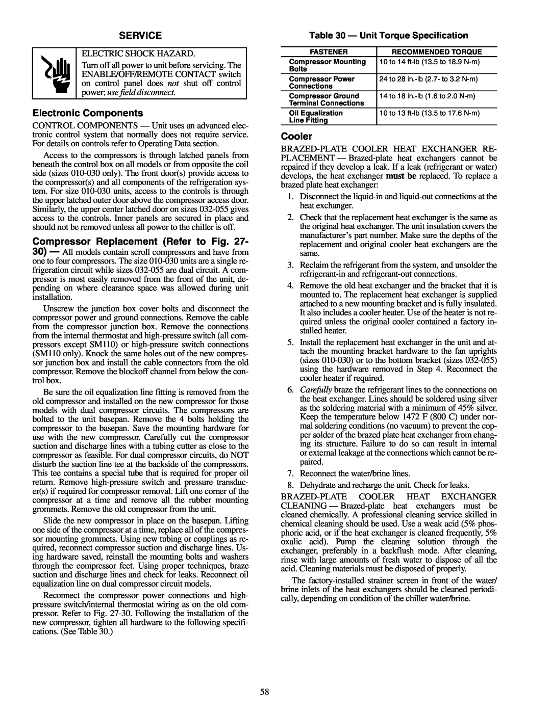
Table 30 — Unit Torque Specification
FASTENER | RECOMMENDED TORQUE |
Compressor Mounting | 10 to 14 |
Bolts |
|
Compressor Power | 24 to 28 |
Connections |
|
Compressor Ground | 14 to 18 |
Terminal Connections |
|
Oil Equalization | 10 to 13 |
Line Fitting |
|
Cooler
1.Disconnect the
2.Check that the replacement heat exchanger is the same as the original heat exchanger. The unit insulation covers the manufacturer’s part number. Make sure the depths of the replacement and original cooler heat exchangers are the same.
3.Reclaim the refrigerant from the system, and unsolder the
4.Remove the old heat exchanger and the bracket that it is mounted to. The replacement heat exchanger is supplied attached to a new mounting bracket and is fully insulated. It also includes a cooler heater. Use of the heater is not re- quired unless the original cooler contained a factory in- stalled heater.
5.Install the replacement heat exchanger in the unit and at- tach the mounting bracket hardware to the fan uprights (sizes
6.Carefully braze the refrigerant lines to the connections on the heat exchanger. Lines should be soldered using silver as the soldering material with a minimum of 45% silver. Keep the temperature below 1472 F (800 C) under nor- mal soldering conditions (no vacuum) to prevent the cop- per solder of the brazed plate heat exchanger from chang- ing its structure. Failure to do so can result in internal or external leakage at the connections which cannot be re- paired.
7.Reconnect the water/brine lines.
8.Dehydrate and recharge the unit. Check for leaks.
The
58