Manuals
/
Sterling
/
Kitchen Appliance
/
Refrigerator
Sterling
30RA010-055
manual
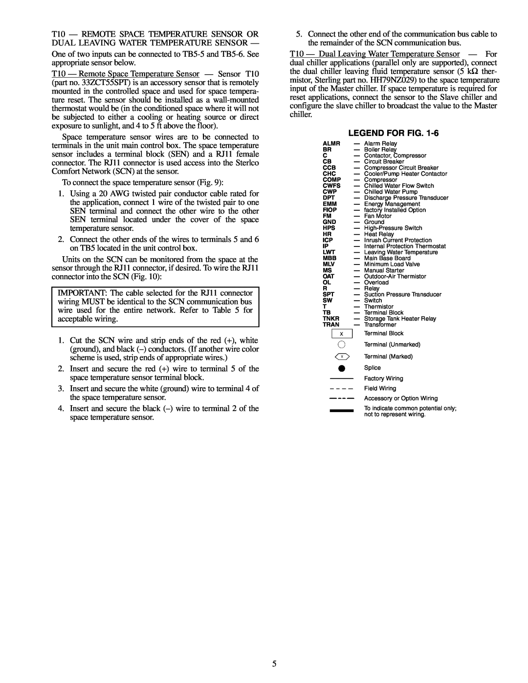
Legend For Fig
Models:
30RA010-055
1
5
100
100
Download
100 pages
44.39 Kb
1
2
3
4
5
6
7
8
Troubleshooting
Error messages
Alarm
Compressor Wiring
Maintenance
OPTIONS1 Options Configuration
A — 4-20mA Reset
30RA Access Panels
DISPLAY Marquee Display SETUP
Main Base Board, J8 Connector
Page 5
Image 5
Page 4
Page 6
Page 5
Image 5
Page 4
Page 6
Contents
SAFETY CONSIDERATIONS
GENERAL
CONTENTS
Control Module Communication
MAJOR SYSTEM COMPONENTS
Sterlco Comfort Network SCN Interface —
Table 1 — Unit Sizes
Table 5 - SCN Communication Bus Wiring
Table 3 — Status Switches
Table 2 — Thermistor Designations
Table 4 - Output Relays
LEGEND FOR FIG.
Page
Page
30RA010-018AQUA SNAP
Fig. 3 — Wiring Schematic 30RA010-018
SEE NOTE SEE NOTE
AQUA-SNAPLOW VOLTAGE CONTROL SCHEMATIC
Fig. 3 - Wiring Schematic 30RA010-018cont
30RA022-030AQUA SNAP
Fig. 4 - Wiring Schematic 30RA022-030
AQUA-SNAPLOW VOLTAGE CONTROL SCHEMATIC
Fig. 4 - Wiring Schematic 30RA022-030cont
30RA032-040AQUA SNAP
Fig. 5 — Wiring Schematic 30RA032-040
AQUA-SNAPLOW VOLTAGE CONTROL SCHEMATIC
Fig. 5 — Wiring Schematic 30RA032-040cont
30RA042-055AQUA SNAP
Fig. 6 — Wiring Schematic 30RA042-055
AQUA-SNAPLOW VOLTAGE CONTROL SCHEMATIC
Fig. 6 — Wiring Schematic 30RA042-055cont
ESCAPEENTER
Fig. 7 — Main Base Board
REMOTE CONTACT SW1 OFF ENABLE OFF SW2 ON
MODE
Fig. 9 — Typical Space Temperature Sensor Wiring
CEPL130351
Fig. 11 - Energy Management Module
100/100
Fig. 12 — Deadband Multiplier
Fig. 14 — 30RA Condenser Fan Sequence
Fig. 13 — Operating Envelope for
R-22Maneurop Compressor
Cooling Set Point Select
and control circuit power must be on
Service Test See Table 11 — Both main power
Table 8 — Control Methods and Cooling Set Points
Fig. 16 — Scrolling Marquee Display
Optional Factory-InstalledHydronic Package —
•Cooler Pump Control CPC Configuration, OPT1 ON
Table 9 — Marquee Display Menu Structure
Fig. 17 — Dual Chiller Thermistor Location
Table 10 — Run Status Mode and Sub-ModeDirectory
SUB-MODE
Table 12 - Temperature Mode and Sub-ModeDirectory
Table 15 — Inputs Mode and Sub-ModeDirectory
Table 13 — Pressure Mode and Sub-ModeDirectory
Table 14 — Set Point and Sub-ModeDirectory
SUB-MODE
Table 16 — Outputs Mode and Sub-ModeDirectory
KEYPAD
DISPLAY
KEYPAD
SUB-MODE
ITEM
DISPLAY
KEYPAD
SUB-MODE
ITEM
DISPLAY
Table 18 — Time Clock Mode and Sub-ModeDirectory
PER.3
SUB-MODE
Table 19 — Operating Mode and Sub-ModeDirectory
Table 20 — Alarms Mode and Sub-ModeDirectory
ITEM
SUB-MODE
KEYPAD ENTRY
DISPLAY
RSET
DISP
Table 23 — Operating Modes
Table 25A — 4-20mA Reset
Table 24 — Example of Reading and Clearing Alarms
Table 26B — Configuring Return Temperature Reset
Temperature Control — No Reset
Fig. 18 — Standard Chilled Fluid
Fig. 19 — Outdoor-AirTemperature Reset
Fig. 20 — Space Temperature Reset
Fig. 21B — Cooling Set Point 4 to 20 mA
Fig. 21A — 4- to 20-mADemand Limiting
Table 27 — Configuring Demand Limit
TROUBLESHOOTING
and fluid tubing
Table 28 — Troubleshooting
Recommended that system be filled with an appro
FU — Fuse GND — Ground
Fig. 22 — Component Arrangement — 30RA010-030
FU — Fuse GND — Ground
Fig. 23 — Component Arrangement — 30RA032-040
FU — Fuse GND — Ground
Fig. 24 — Component Arrangement — 30RA042-055
NOTES
LEGEND
Table 29 — Alarm and Alert Codes
Table 29 - Alarm and Alert Codes cont
ALARM
Table 29 — Alarm and Alert Codes cont
ALARM
Table 29 — Alarm and Alert Codes cont
ALARM
Table 29 — Alarm and Alert Codes cont
Compressor Replacement Refer to Fig
SERVICE
Table 30 - Unit Torque Specification
Electronic Components
Fig. 27 — Typical Compressor Mounting — All Sizes
Fig. 28 — Compressor Wiring
Fig. 29 — Compressor Location — 30RA010-030
Fig. 30 — Compressor Location — 30RA032-055
Table 31 - Oil Charge
Condenser Section and Coils
Check Refrigerant Feed Components
Fig. 31 — 30RA Access Panels
Fig. 32 — Condenser-FanMounting
Fig. 33 — Condenser-FanPosition Standard Fan
Switch Fixed
Table 32 — Factory Settings, High-Pressure
Compressor and Unit Protective Devices
Check Unit Safeties
COOLER FREEZE-UPPROTECTION
TEMP
TEMP
For Thermistor T10
For Thermistor T10
Fig. 36 — Thermistor Connections to
Main Base Board, J8 Connector
Fig. 35 — Fluid-SideTemperature Sensors T1 and T2
PROGRAMMING
Mode
•P51: SOFTWARE version
Table 37 - Fault Codes
•P50: FAULT HISTORY — Last 8 faults
PARAMETERS
Table 39 — Replacement Modules
Minimum Loop Volume
MAINTENANCE
PRE-START-UP
System Check
Operating Limitations
Standard 30RA Units
OPERATION SEQUENCE
Table 41 — Temperature Limits for
SCN Tables A_UNIT General Unit Parameters
APPENDIX A
CIRCADIO Circuit A Discrete Inputs/Outputs
CIRCA_AN Circuit A Analog Parameters
OPTIONS Unit Parameters
CIRCBDIO Circuit B Discrete Inputs/Outputs
CIRCB_AN Circuit B Analog Parameters
DISPLAY Marquee Display SETUP
ALARMDEF Alarm Definition Table
DUALCHIL Dual Chiller Configuration Settings
BRODEFS Broadcast POC Definition Table
OPTIONS2 Options 2 Configuration
OPTIONS1 Options 1 Configuration
SETPOINT
SCHEDOVR Timed Override Setup
RESETCON Temperature Reset and Demand Limit
MAINTENANCE
ALARMS: Maintenance Display
UNIT
DUALCHIL: Maintenance Display
CURRMODS: Maintenance Display
LOADFACT: Maintenance Display
LEARNFNS Maintenance Display
PM-STRN Maintenance Display
PM-COIL:Maintenance Display
PM-PUMP:Maintenance Display
RUNTEST: Maintenance Display
VERSIONS: Maintenance Display
STRTHOUR Maintenance Display
TESTMODE: Maintenance Display
WSMDEFME: Maintenance Display
AND MANUAL STARTERS
FACTORY SETTINGS FOR COMPRESSOR, FAN, PUMP
APPENDIX B
FACTORY SETTINGS FOR COMPRESSOR, FAN, PUMP
AND MANUAL STARTERS cont
DataPort, DataLink, BAClink Object Definition
APPENDIX C
SETPOINT
OPTIONS
Remove and use for Job File I.Project Information
START-UPCHECKLIST FOR 30RA LIQUID CHILLER
II. Preliminary Equipment Check
Design Information
Start and Operate Machine. Complete the Following
III. Unit Start-Up
CL-3
CL-4
Record Software Versions MODE — RUN STATUS
COMMENTS
III.Unit Start-Upcont
UNIT Configuration Settings
OPTIONS1 Options Configuration
RSET Reset Configuration Settings
OPTIONS2 Options Configuration
III.Unit Start-Upcont
CL-6
III.Unit Start-Upcont
SLCT Setpoint and Ramp Load Configuration
SETPOINT
CL-7
III.Unit Start-Upcont
Service Test Mode and Sub-ModeDirectory
Top
Page
Image
Contents