APPENDIX C
Building Interface — The 30RAN chiller can be inter- faced with
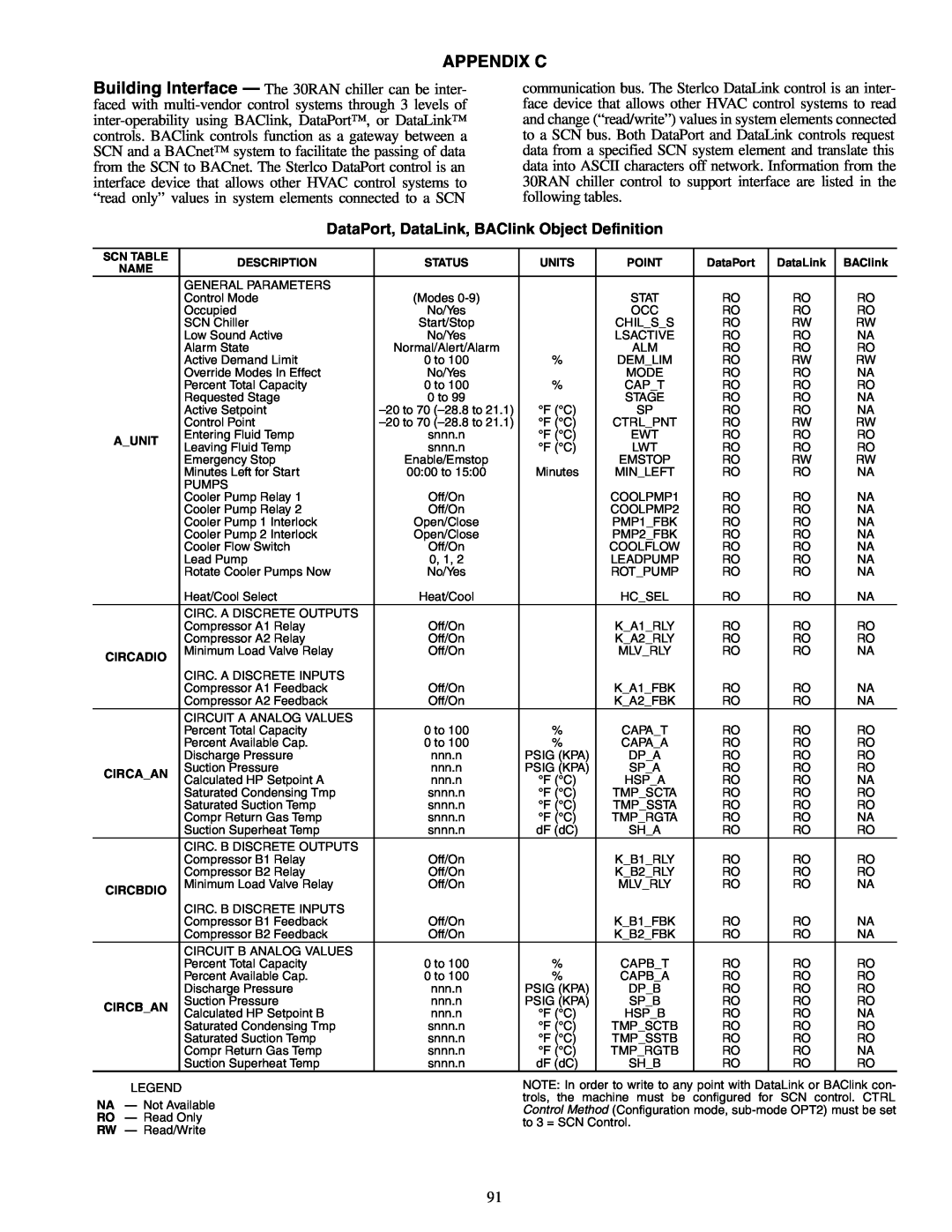
communication bus. The Sterlco DataLink control is an inter- face device that allows other HVAC control systems to read and change (“read/write”) values in system elements connected to a SCN bus. Both DataPort and DataLink controls request data from a specified SCN system element and translate this data into ASCII characters off network. Information from the 30RAN chiller control to support interface are listed in the following tables.
DataPort, DataLink, BAClink Object Definition
SCN TABLE | DESCRIPTION | STATUS | UNITS | POINT | DataPort | DataLink | BAClink | |
NAME | ||||||||
|
|
|
|
|
|
| ||
| GENERAL PARAMETERS |
|
|
|
|
|
| |
| Control Mode | (Modes |
| STAT | RO | RO | RO | |
| Occupied | No/Yes |
| OCC | RO | RO | RO | |
| SCN Chiller | Start/Stop |
| CHIL_S_S | RO | RW | RW | |
| Low Sound Active | No/Yes |
| LSACTIVE | RO | RO | NA | |
| Alarm State | Normal/Alert/Alarm |
| ALM | RO | RO | RO | |
| Active Demand Limit | 0 to 100 | % | DEM_LIM | RO | RW | RW | |
| Override Modes In Effect | No/Yes |
| MODE | RO | RO | NA | |
| Percent Total Capacity | 0 to 100 | % | CAP_T | RO | RO | RO | |
| Requested Stage | 0 to 99 |
| STAGE | RO | RO | NA | |
| Active Setpoint | °F (°C) | SP | RO | RO | NA | ||
| Control Point | °F (°C) | CTRL_PNT | RO | RW | RW | ||
A_UNIT | Entering Fluid Temp | snnn.n | °F (°C) | EWT | RO | RO | RO | |
Leaving Fluid Temp | snnn.n | °F (°C) | LWT | RO | RO | RO | ||
| ||||||||
| Emergency Stop | Enable/Emstop |
| EMSTOP | RO | RW | RW | |
| Minutes Left for Start | 00:00 to 15:00 | Minutes | MIN_LEFT | RO | RO | NA | |
| PUMPS |
|
|
|
|
|
| |
| Cooler Pump Relay 1 | Off/On |
| COOLPMP1 | RO | RO | NA | |
| Cooler Pump Relay 2 | Off/On |
| COOLPMP2 | RO | RO | NA | |
| Cooler Pump 1 Interlock | Open/Close |
| PMP1_FBK | RO | RO | NA | |
| Cooler Pump 2 Interlock | Open/Close |
| PMP2_FBK | RO | RO | NA | |
| Cooler Flow Switch | Off/On |
| COOLFLOW | RO | RO | NA | |
| Lead Pump | 0, 1, 2 |
| LEADPUMP | RO | RO | NA | |
| Rotate Cooler Pumps Now | No/Yes |
| ROT_PUMP | RO | RO | NA | |
| Heat/Cool Select | Heat/Cool |
| HC_SEL | RO | RO | NA | |
| CIRC. A DISCRETE OUTPUTS |
|
|
|
|
|
| |
| Compressor A1 Relay | Off/On |
| K_A1_RLY | RO | RO | RO | |
| Compressor A2 Relay | Off/On |
| K_A2_RLY | RO | RO | RO | |
CIRCADIO | Minimum Load Valve Relay | Off/On |
| MLV_RLY | RO | RO | NA | |
|
|
|
|
|
|
| ||
| CIRC. A DISCRETE INPUTS |
|
|
|
|
|
| |
| Compressor A1 Feedback | Off/On |
| K_A1_FBK | RO | RO | NA | |
| Compressor A2 Feedback | Off/On |
| K_A2_FBK | RO | RO | NA | |
| CIRCUIT A ANALOG VALUES | 0 to 100 | % |
|
|
| RO | |
| Percent Total Capacity | CAPA_T | RO | RO | ||||
| Percent Available Cap. | 0 to 100 | % | CAPA_A | RO | RO | RO | |
| Discharge Pressure | nnn.n | PSIG (KPA) | DP_A | RO | RO | RO | |
CIRCA_AN | Suction Pressure | nnn.n | PSIG (KPA) | SP_A | RO | RO | RO | |
Calculated HP Setpoint A | nnn.n | °F (°C) | HSP_A | RO | RO | NA | ||
| ||||||||
| Saturated Condensing Tmp | snnn.n | °F (°C) | TMP_SCTA | RO | RO | RO | |
| Saturated Suction Temp | snnn.n | °F (°C) | TMP_SSTA | RO | RO | RO | |
| Compr Return Gas Temp | snnn.n | °F (°C) | TMP_RGTA | RO | RO | NA | |
| Suction Superheat Temp | snnn.n | dF (dC) | SH_A | RO | RO | RO | |
| CIRC. B DISCRETE OUTPUTS |
|
|
|
|
|
| |
| Compressor B1 Relay | Off/On |
| K_B1_RLY | RO | RO | RO | |
| Compressor B2 Relay | Off/On |
| K_B2_RLY | RO | RO | RO | |
CIRCBDIO | Minimum Load Valve Relay | Off/On |
| MLV_RLY | RO | RO | NA | |
|
|
|
|
|
|
| ||
| CIRC. B DISCRETE INPUTS |
|
|
|
|
|
| |
| Compressor B1 Feedback | Off/On |
| K_B1_FBK | RO | RO | NA | |
| Compressor B2 Feedback | Off/On |
| K_B2_FBK | RO | RO | NA | |
| CIRCUIT B ANALOG VALUES |
|
|
|
|
|
| |
| Percent Total Capacity | 0 to 100 | % | CAPB_T | RO | RO | RO | |
| Percent Available Cap. | 0 to 100 | % | CAPB_A | RO | RO | RO | |
| Discharge Pressure | nnn.n | PSIG (KPA) | DP_B | RO | RO | RO | |
CIRCB_AN | Suction Pressure | nnn.n | PSIG (KPA) | SP_B | RO | RO | RO | |
Calculated HP Setpoint B | nnn.n | °F (°C) | HSP_B | RO | RO | NA | ||
| ||||||||
| Saturated Condensing Tmp | snnn.n | °F (°C) | TMP_SCTB | RO | RO | RO | |
| Saturated Suction Temp | snnn.n | °F (°C) | TMP_SSTB | RO | RO | RO | |
| Compr Return Gas Temp | snnn.n | °F (°C) | TMP_RGTB | RO | RO | NA | |
| Suction Superheat Temp | snnn.n | dF (dC) | SH_B | RO | RO | RO |
LEGEND
NA — Not Available
RO — Read Only
RW — Read/Write
NOTE: In order to write to any point with DataLink or BAClink con- trols, the machine must be configured for SCN control. CTRL Control Method (Configuration mode,
91