| 100 |
|
|
|
|
|
|
| 50% CAPACITY AT 20 mA |
| ||
|
|
|
|
|
|
|
|
|
| |||
(%) |
|
|
|
|
|
|
|
|
|
|
|
|
LOAD | 80 |
|
|
|
|
|
|
|
|
|
|
|
|
|
|
|
|
|
|
|
|
|
|
| |
ALLOWABLE.MAX | 60 |
|
|
|
|
|
|
|
|
|
|
|
40 | 100% CAPACITY AT 4 mA |
| 75% CAPACITY AT 12 mA |
|
|
|
|
| ||||
|
|
|
|
|
|
|
|
|
| |||
20 |
|
|
|
|
|
|
|
|
|
|
| |
| 0 | 0 | 2 | 4 | 6 | 8 | 10 | 12 | 14 | 16 | 18 | 20 |
|
|
|
|
|
| DEMAND LIMIT SIGNAL – 4 - 20 mA INPUT |
|
|
| |||
|
|
|
|
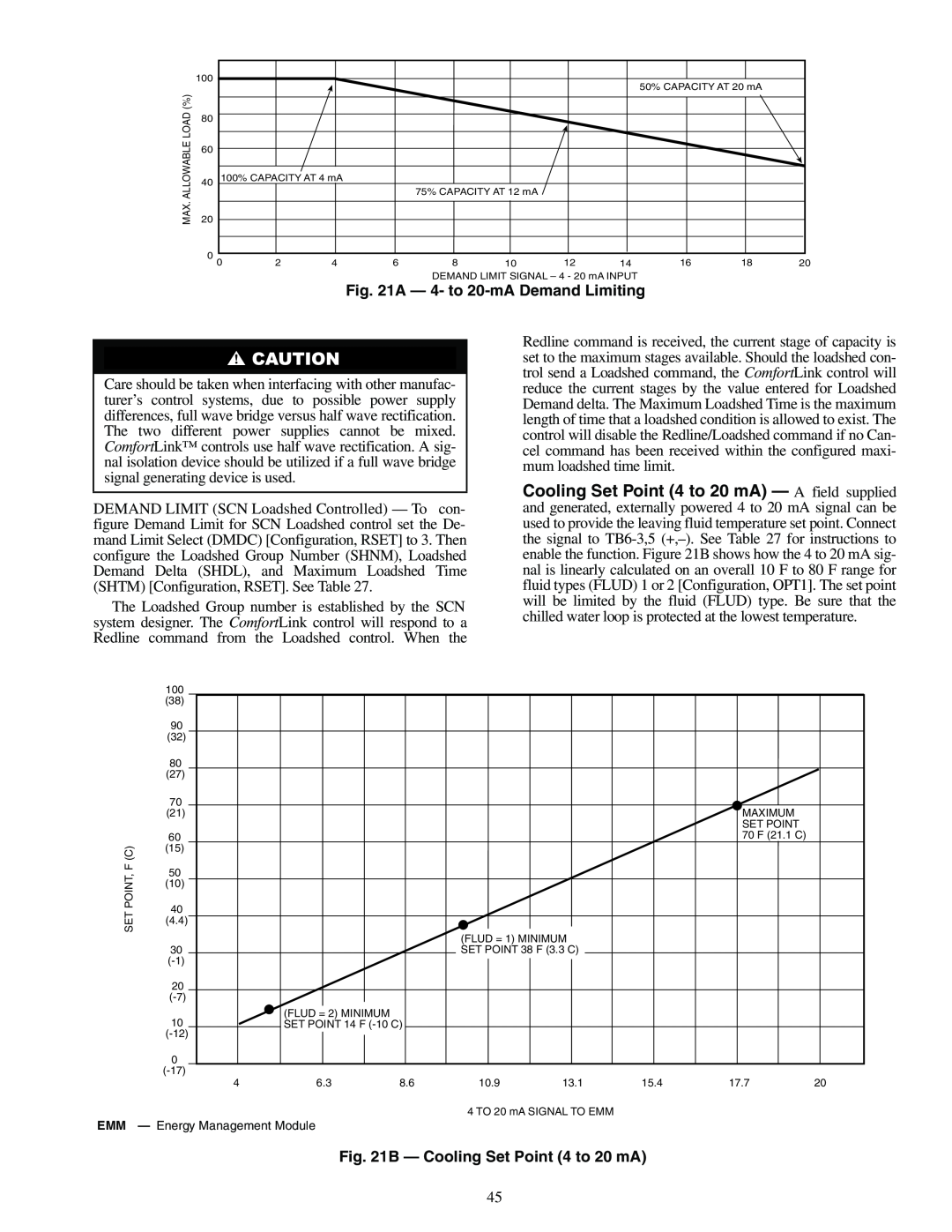
| Fig. 21A — 4- to |
|
|
| ||||
Care should be taken when interfacing with other manufac- turer’s control systems, due to possible power supply differences, full wave bridge versus half wave rectification. The two different power supplies cannot be mixed. ComfortLink™ controls use half wave rectification. A sig- nal isolation device should be utilized if a full wave bridge signal generating device is used.
DEMAND LIMIT (SCN Loadshed Controlled) — To con- figure Demand Limit for SCN Loadshed control set the De- mand Limit Select (DMDC) [Configuration, RSET] to 3. Then configure the Loadshed Group Number (SHNM), Loadshed Demand Delta (SHDL), and Maximum Loadshed Time (SHTM) [Configuration, RSET]. See Table 27.
The Loadshed Group number is established by the SCN system designer. The ComfortLink control will respond to a Redline command from the Loadshed control. When the
Redline command is received, the current stage of capacity is set to the maximum stages available. Should the loadshed con- trol send a Loadshed command, the ComfortLink control will reduce the current stages by the value entered for Loadshed Demand delta. The Maximum Loadshed Time is the maximum length of time that a loadshed condition is allowed to exist. The control will disable the Redline/Loadshed command if no Can- cel command has been received within the configured maxi- mum loadshed time limit.
Cooling Set Point (4 to 20 mA) — A field supplied and generated, externally powered 4 to 20 mA signal can be used to provide the leaving fluid temperature set point. Connect the signal to
| 100 |
|
|
|
|
|
|
|
| (38) |
|
|
|
|
|
|
|
| 90 |
|
|
|
|
|
|
|
| (32) |
|
|
|
|
|
|
|
| 80 |
|
|
|
|
|
|
|
| (27) |
|
|
|
|
|
|
|
| 70 |
|
|
|
|
|
|
|
| (21) |
|
|
|
|
| MAXIMUM |
|
|
|
|
|
|
|
| SET POINT |
|
| 60 |
|
|
|
|
| 70 F (21.1 C) |
|
F (C) | (15) |
|
|
|
|
|
|
|
50 |
|
|
|
|
|
|
| |
POINT, |
|
|
|
|
|
|
| |
(10) |
|
|
|
|
|
|
| |
40 |
|
|
|
|
|
|
| |
SET |
|
|
|
|
|
|
| |
(4.4) |
|
|
|
|
|
|
| |
|
|
| (FLUD = 1) MINIMUM |
|
|
| ||
|
|
|
|
|
|
| ||
| 30 |
|
| SET POINT 38 F (3.3 C) |
|
|
| |
|
|
|
|
|
|
|
| |
| 20 |
|
|
|
|
|
|
|
|
|
|
|
|
|
|
| |
| 10 | (FLUD = 2) MINIMUM |
|
|
|
|
|
|
| SET POINT 14 F |
|
|
|
|
| ||
|
|
|
|
|
|
|
| |
| 0 |
|
|
|
|
|
|
|
|
|
|
|
|
|
|
| |
| 4 | 6.3 | 8.6 | 10.9 | 13.1 | 15.4 | 17.7 | 20 |
4 TO 20 mA SIGNAL TO EMM
EMM — Energy Management Module
Fig. 21B — Cooling Set Point (4 to 20 mA)
45