Manuals
/
Sterling
/
Kitchen Appliance
/
Refrigerator
Sterling
30RA010-055 Operating Envelope for, R-22Maneurop Compressor, 30RA Condenser Fan Sequence
Models:
30RA010-055
1
21
100
100
Download
100 pages
44.39 Kb
18
19
20
21
22
23
24
25
Troubleshooting
Error messages
Alarm
Compressor Wiring
Maintenance
OPTIONS1 Options Configuration
A — 4-20mA Reset
30RA Access Panels
DISPLAY Marquee Display SETUP
Main Base Board, J8 Connector
Page 21
Image 21
Page 20
Page 22
Page 21
Image 21
Page 20
Page 22
Contents
SAFETY CONSIDERATIONS
GENERAL
CONTENTS
Control Module Communication
MAJOR SYSTEM COMPONENTS
Sterlco Comfort Network SCN Interface —
Table 1 — Unit Sizes
Table 5 - SCN Communication Bus Wiring
Table 3 — Status Switches
Table 2 — Thermistor Designations
Table 4 - Output Relays
LEGEND FOR FIG.
Page
Page
30RA010-018AQUA SNAP
Fig. 3 — Wiring Schematic 30RA010-018
AQUA-SNAPLOW VOLTAGE CONTROL SCHEMATIC
Fig. 3 - Wiring Schematic 30RA010-018cont
SEE NOTE SEE NOTE
30RA022-030AQUA SNAP
Fig. 4 - Wiring Schematic 30RA022-030
AQUA-SNAPLOW VOLTAGE CONTROL SCHEMATIC
Fig. 4 - Wiring Schematic 30RA022-030cont
30RA032-040AQUA SNAP
Fig. 5 — Wiring Schematic 30RA032-040
AQUA-SNAPLOW VOLTAGE CONTROL SCHEMATIC
Fig. 5 — Wiring Schematic 30RA032-040cont
30RA042-055AQUA SNAP
Fig. 6 — Wiring Schematic 30RA042-055
AQUA-SNAPLOW VOLTAGE CONTROL SCHEMATIC
Fig. 6 — Wiring Schematic 30RA042-055cont
ESCAPEENTER
Fig. 7 — Main Base Board
REMOTE CONTACT SW1 OFF ENABLE OFF SW2 ON
MODE
Fig. 9 — Typical Space Temperature Sensor Wiring
CEPL130351
Fig. 11 - Energy Management Module
100/100
Fig. 12 — Deadband Multiplier
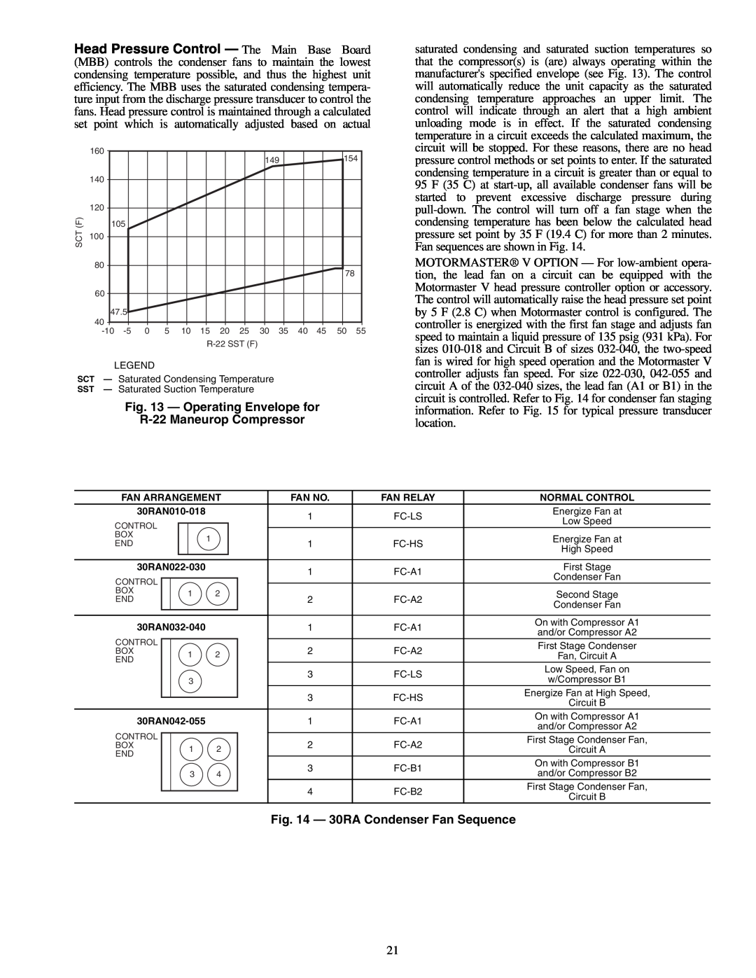
Fig. 13 — Operating Envelope for
R-22Maneurop Compressor
Fig. 14 — 30RA Condenser Fan Sequence
Cooling Set Point Select
and control circuit power must be on
Service Test See Table 11 — Both main power
Table 8 — Control Methods and Cooling Set Points
Fig. 16 — Scrolling Marquee Display
Optional Factory-InstalledHydronic Package —
•Cooler Pump Control CPC Configuration, OPT1 ON
Table 9 — Marquee Display Menu Structure
Fig. 17 — Dual Chiller Thermistor Location
Table 10 — Run Status Mode and Sub-ModeDirectory
SUB-MODE
Table 12 - Temperature Mode and Sub-ModeDirectory
Table 13 — Pressure Mode and Sub-ModeDirectory
Table 14 — Set Point and Sub-ModeDirectory
Table 15 — Inputs Mode and Sub-ModeDirectory
SUB-MODE
Table 16 — Outputs Mode and Sub-ModeDirectory
KEYPAD
DISPLAY
KEYPAD
SUB-MODE
ITEM
DISPLAY
KEYPAD
SUB-MODE
ITEM
DISPLAY
Table 18 — Time Clock Mode and Sub-ModeDirectory
PER.3
SUB-MODE
Table 19 — Operating Mode and Sub-ModeDirectory
Table 20 — Alarms Mode and Sub-ModeDirectory
ITEM
SUB-MODE
KEYPAD ENTRY
DISPLAY
RSET
DISP
Table 23 — Operating Modes
Table 25A — 4-20mA Reset
Table 24 — Example of Reading and Clearing Alarms
Table 26B — Configuring Return Temperature Reset
Temperature Control — No Reset
Fig. 18 — Standard Chilled Fluid
Fig. 19 — Outdoor-AirTemperature Reset
Fig. 20 — Space Temperature Reset
Fig. 21B — Cooling Set Point 4 to 20 mA
Fig. 21A — 4- to 20-mADemand Limiting
Table 27 — Configuring Demand Limit
TROUBLESHOOTING
Table 28 — Troubleshooting
Recommended that system be filled with an appro
and fluid tubing
FU — Fuse GND — Ground
Fig. 22 — Component Arrangement — 30RA010-030
FU — Fuse GND — Ground
Fig. 23 — Component Arrangement — 30RA032-040
FU — Fuse GND — Ground
Fig. 24 — Component Arrangement — 30RA042-055
NOTES
LEGEND
Table 29 — Alarm and Alert Codes
Table 29 - Alarm and Alert Codes cont
ALARM
Table 29 — Alarm and Alert Codes cont
ALARM
Table 29 — Alarm and Alert Codes cont
ALARM
Table 29 — Alarm and Alert Codes cont
Compressor Replacement Refer to Fig
SERVICE
Table 30 - Unit Torque Specification
Electronic Components
Fig. 27 — Typical Compressor Mounting — All Sizes
Fig. 28 — Compressor Wiring
Fig. 29 — Compressor Location — 30RA010-030
Fig. 30 — Compressor Location — 30RA032-055
Table 31 - Oil Charge
Condenser Section and Coils
Check Refrigerant Feed Components
Fig. 31 — 30RA Access Panels
Fig. 32 — Condenser-FanMounting
Fig. 33 — Condenser-FanPosition Standard Fan
Switch Fixed
Table 32 — Factory Settings, High-Pressure
Compressor and Unit Protective Devices
Check Unit Safeties
COOLER FREEZE-UPPROTECTION
TEMP
TEMP
For Thermistor T10
For Thermistor T10
Main Base Board, J8 Connector
Fig. 35 — Fluid-SideTemperature Sensors T1 and T2
Fig. 36 — Thermistor Connections to
PROGRAMMING
Mode
Table 37 - Fault Codes
•P50: FAULT HISTORY — Last 8 faults
•P51: SOFTWARE version
PARAMETERS
Table 39 — Replacement Modules
Minimum Loop Volume
MAINTENANCE
PRE-START-UP
System Check
Operating Limitations
OPERATION SEQUENCE
Table 41 — Temperature Limits for
Standard 30RA Units
SCN Tables A_UNIT General Unit Parameters
APPENDIX A
CIRCADIO Circuit A Discrete Inputs/Outputs
CIRCA_AN Circuit A Analog Parameters
CIRCBDIO Circuit B Discrete Inputs/Outputs
CIRCB_AN Circuit B Analog Parameters
OPTIONS Unit Parameters
DISPLAY Marquee Display SETUP
ALARMDEF Alarm Definition Table
DUALCHIL Dual Chiller Configuration Settings
BRODEFS Broadcast POC Definition Table
OPTIONS2 Options 2 Configuration
OPTIONS1 Options 1 Configuration
SCHEDOVR Timed Override Setup
RESETCON Temperature Reset and Demand Limit
SETPOINT
ALARMS: Maintenance Display
UNIT
MAINTENANCE
DUALCHIL: Maintenance Display
CURRMODS: Maintenance Display
LOADFACT: Maintenance Display
LEARNFNS Maintenance Display
PM-COIL:Maintenance Display
PM-PUMP:Maintenance Display
PM-STRN Maintenance Display
RUNTEST: Maintenance Display
STRTHOUR Maintenance Display
TESTMODE: Maintenance Display
VERSIONS: Maintenance Display
WSMDEFME: Maintenance Display
FACTORY SETTINGS FOR COMPRESSOR, FAN, PUMP
APPENDIX B
AND MANUAL STARTERS
FACTORY SETTINGS FOR COMPRESSOR, FAN, PUMP
AND MANUAL STARTERS cont
DataPort, DataLink, BAClink Object Definition
APPENDIX C
SETPOINT
OPTIONS
Remove and use for Job File I.Project Information
START-UPCHECKLIST FOR 30RA LIQUID CHILLER
II. Preliminary Equipment Check
Design Information
Start and Operate Machine. Complete the Following
III. Unit Start-Up
CL-3
Record Software Versions MODE — RUN STATUS
COMMENTS
CL-4
UNIT Configuration Settings
OPTIONS1 Options Configuration
III.Unit Start-Upcont
RSET Reset Configuration Settings
OPTIONS2 Options Configuration
III.Unit Start-Upcont
CL-6
III.Unit Start-Upcont
SLCT Setpoint and Ramp Load Configuration
SETPOINT
CL-7
III.Unit Start-Upcont
Service Test Mode and Sub-ModeDirectory
Top
Page
Image
Contents